Two-dimensional virtual array probe for three-dimensional ultrasonic imaging

Inactive Publication Date: 2012-08-23
ROBOGEN
View PDF7 Cites 3 Cited by
  • Summary
  • Abstract
  • Description
  • Claims
  • Application Information

AI Technical Summary

Benefits of technology

[0012]According to the present invention, it is possible to provide inspection equipment which has a performance similar to the non-destructive inspection apparatus using the plurality of ultrasonic waves, with only one ultrasonic transducer, thereby reducing a unit price of the non-destructive inspection apparatus.BRIEF DESCRIPTIONS OF THE DRAWINGS
[0013]FIG. 1 is a view illustrating a configuration of a probe of a non-destructive inspection apparatus according to the present invention.
[0014]FIG. 2 is an exploded perspective view of FIG. 1.
[0015]FIG. 3 is a graph of a signal received at an end of a wave-guide prior to time inversion.
[0016]FIG. 4 is a graph of a signal in which the signal of FIG. 3 is time-inverted.
[0017]FIGS. 5 and 6 are graphs showing pulse signals focused on a time axis, which are generated through ultrasonic transducer using software.

Problems solved by technology

However, according to this configuration, since the ultrasonic transducers have to be provided for each channel, there is a problem of highly costing for configuring a system.
However, the method disclosed in the paper has a problem that a plurality of transducers are also used and ultrasonic beam is rapidly spread after being focused at a focal point due to a characteristic of a time inversion method of the related art.
That is, since the ultrasonic wave generated from the transducer is not transmitted in parallel to the object to be inspected and has a property of instantly spreading after being focused at the focal point, there is a problem having a difficulty in implementing the pulse-echo type non-destructive inspection using such a sound beam.

Method used


Image

  • Two-dimensional virtual array probe for three-dimensional ultrasonic imaging
  • Two-dimensional virtual array probe for three-dimensional ultrasonic imaging
  • Two-dimensional virtual array probe for three-dimensional ultrasonic imaging

Examples


Embodiment Construction

Problems to be Solved by the Invention

[0006]The present invention have been made in view of the above problems, and unlike a 2-dimensional array probe including thousands of the piezoelectric-elements in the related art, provide a 2-dimensional virtual array probe for 3-dimensional ultrasonic imaging, of which structure is improved to generate an irregular internal reflection.

Means for Solving the Problem

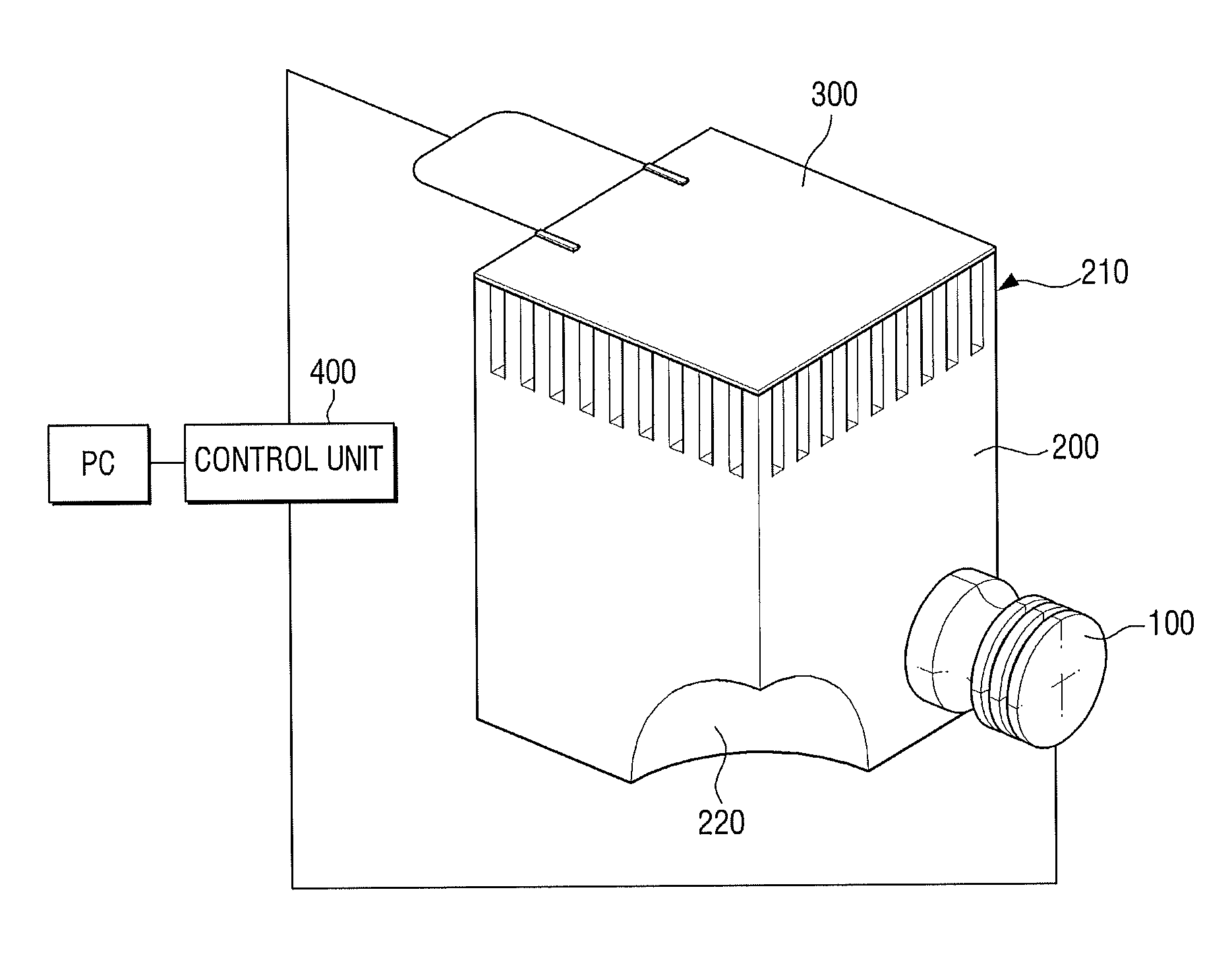
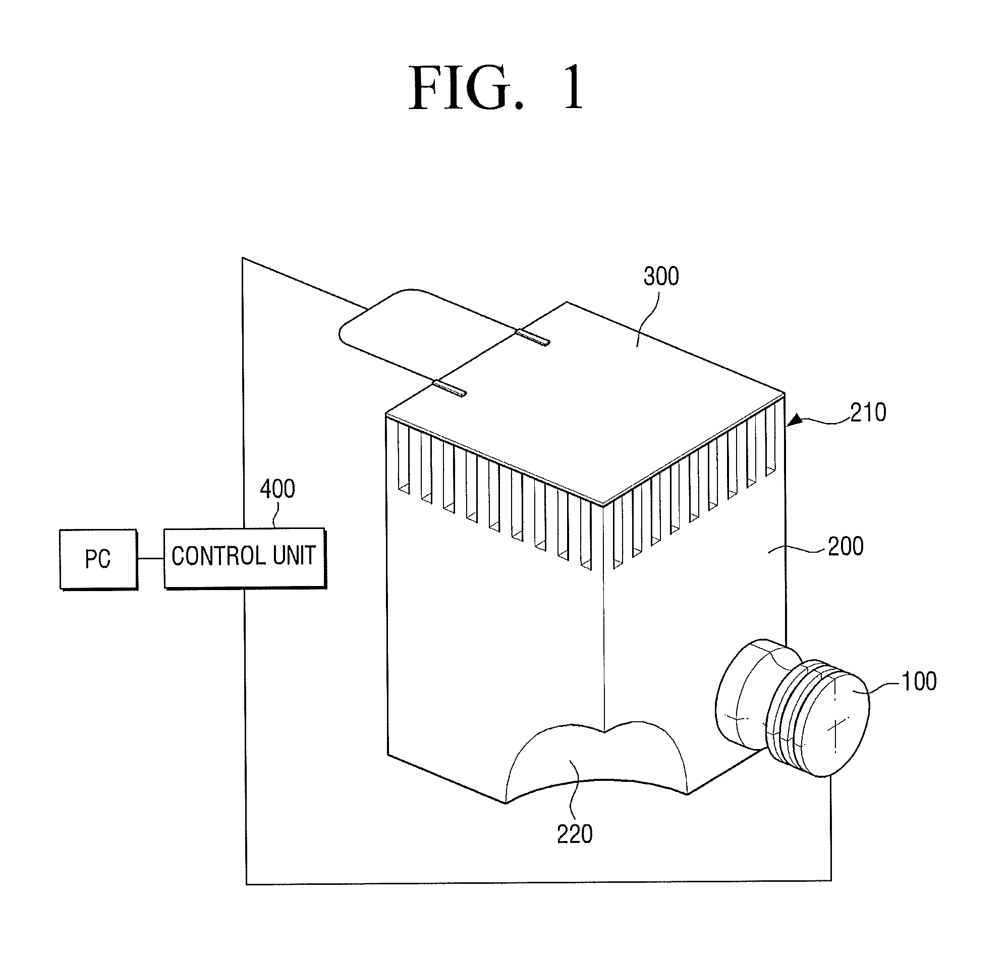
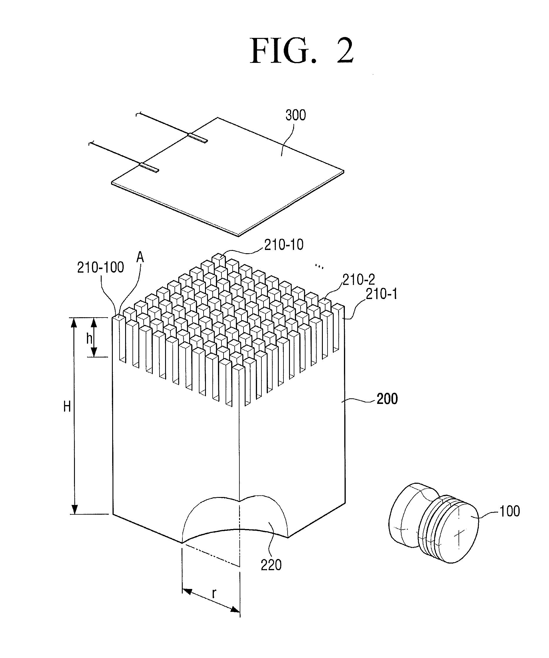
[0007]The 2-dimensional virtual array probe for 3-dimensional ultrasonic imaging includes: an ultrasonic transducer; a metallic probe body including an ultrasonic wave emission surface in which a plurality of wave-guides are arranged in 2-dimensional array and a ⅛ sphere-shaped recess for irregularly reflecting ultrasonic wave emitted from the ultrasonic transducer in an inside thereof; a piezoelectric sheet arranged on the ultrasonic wave emission surface to make contact with an object to be inspected and configured to pass the ultrasonic waves emitted from the probe toward the obj...


PUM


Abstract

Provided is a 2-dimensional virtual array probe for 3-dimensional ultrasonic imaging. The probe includes: an ultrasonic transducer; a metallic probe body including an ultrasonic wave emission surface in which a plurality of wave-guides are arranged in 2-dimensional array and a ⅛ sphere-shaped recess for irregularly reflecting ultrasonic wave emitted from the ultrasonic transducer in an inside thereof; a piezoelectric sheet arranged on the ultrasonic wave emission surface to make contact with an object to be inspected and configured to pass the ultrasonic waves emitted from the probe toward the object to be inspected and output a signal by detecting the ultrasonic waves reflected from the object to be detected; and a control unit configured to control the ultrasonic transducer so that the plurality of wave-guides sequentially generate ultrasonic wave.

Description

FIELD OF THE INVENTION[0001]The present invention relates to development of an ultrasonic probe, which is used for ultrasonic image diagnosis and non-destructive inspection, and more particularly, to a 2-dimensional virtual array probe for real-time 3-dimensional ultrasonic imaging.BACKGROUND ART[0002]In general, a widely used 2-dimension array probe includes piezoelectric elements as many as thousands, forms an array by fixedly arranging ultrasonic transducers at regular intervals, which are capable of transmitting / receiving ultra-sonic waves, and detects a defect in an object to be inspected by using a pulse-echo method.[0003]As an example of currently commercialized ultrasonic non-destructive inspection apparatus, a 60×60 array probe may be exemplified. In this case, total 3600 ultrasonic transducers are needed and the respective 3600 ultrasonic transducers are controlled using the respective 3600 channels to obtain a 3-dimensional image. However, according to this configuration,...

Claims


Application Information

Patent Timeline
IPC IPC(8): G01N29/24
CPCG01N2291/106G01N29/2437G01N29/24G01Q70/08
Inventor OHM, WON-SUKCHOI, YOUNG-SOO
Owner ROBOGEN
Why Eureka
Try Eureka