
Cutting insert, cutting tool, and method of manufacturing machined product using the same

a technology of cutting tools and cutting inserts, which is applied in the direction of cutting inserts, manufacturing tools, shaping cutters, etc., can solve the problems that chips generated from workpieces with rich ductility cannot be smoothly discharged backward (outward) and achieve the effects of rich ductility, easy chip division, and increased wear resistan

Active Publication Date: 2012-08-23
KYOCERA CORP
View PDF10 Cites 9 Cited by
  • Summary
  • Abstract
  • Description
  • Claims
  • Application Information

AI Technical Summary

Benefits of technology

[0005]An object of the present invention is to provide a cutting insert and a cutting tool, which have excellent chip discharge performance, and a method of manufacturing a machined product using the cutting tool.
[0009]A method of manufacturing a machined product according to an embodiment of the present invention includes rotating a workpiece; bringing the workpiece being rotated and the cutting edge of the cutting tool into contact with each other; and allowing the workpiece and the cutting tool to be separated from each other.
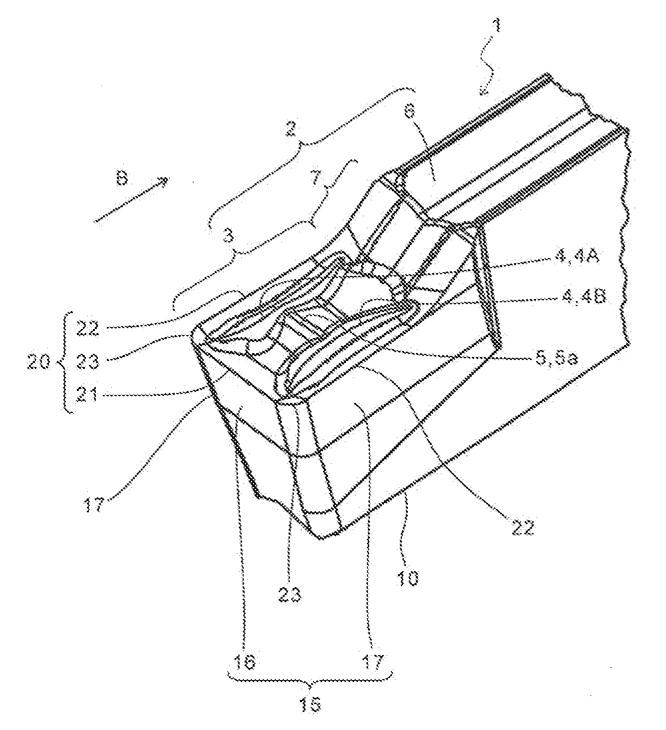
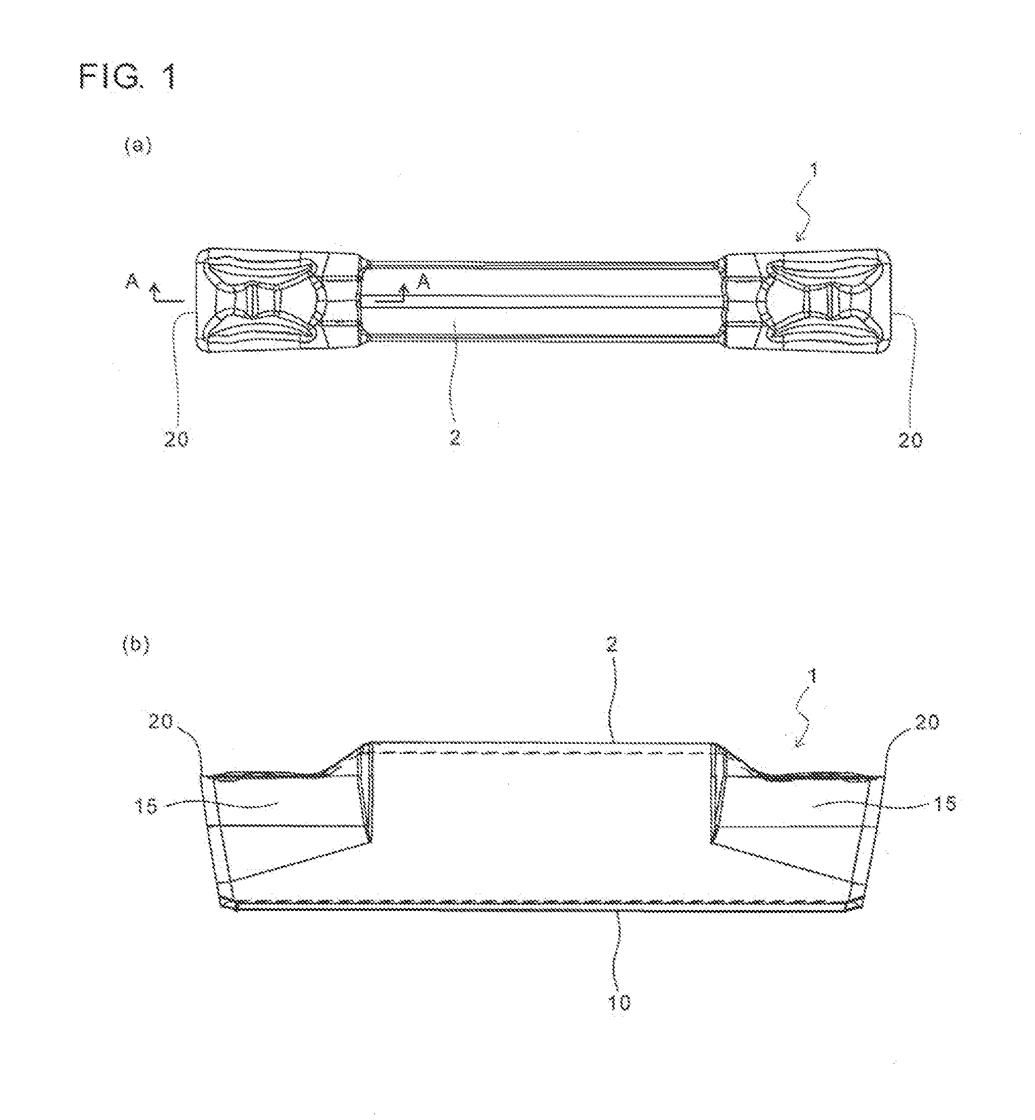
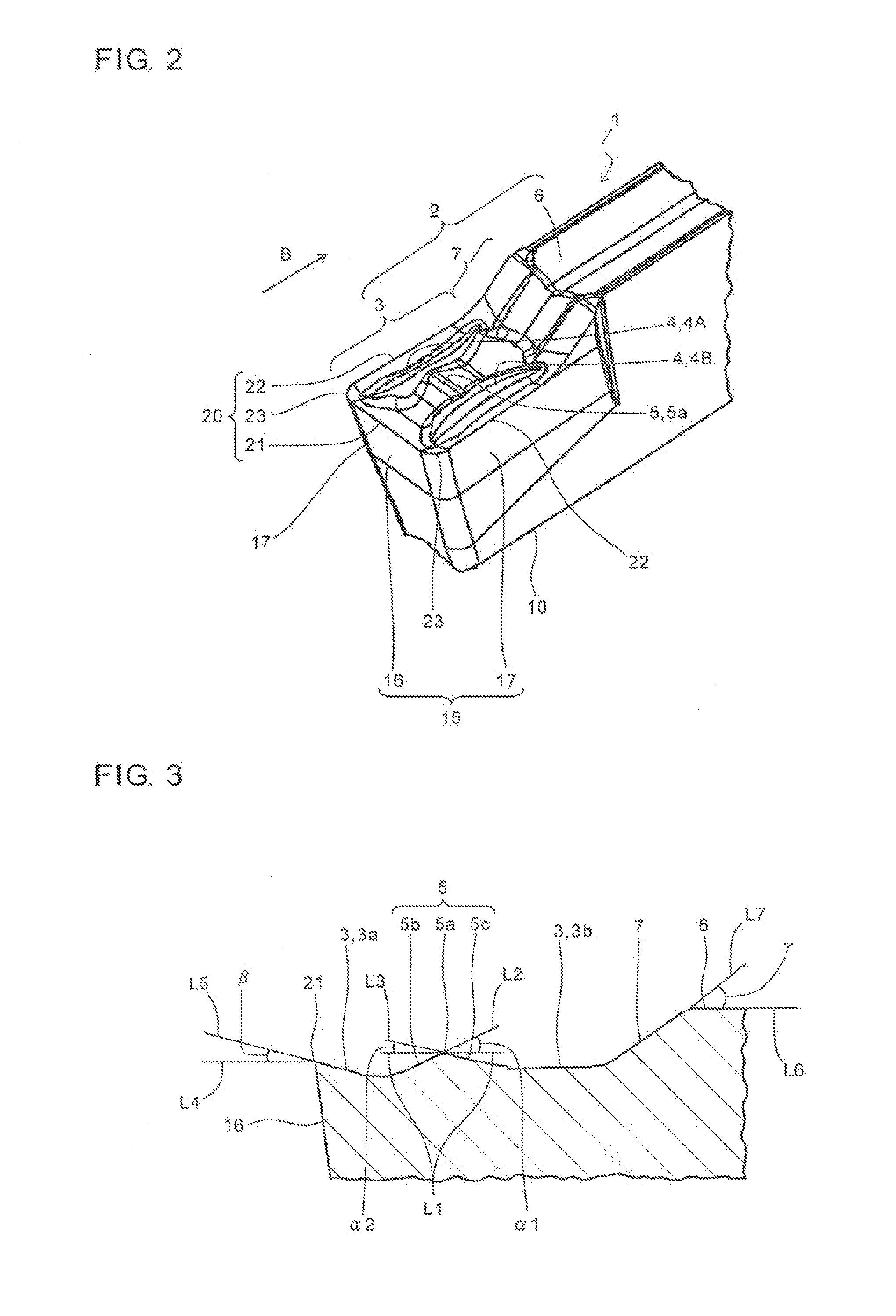
[0010]In the cutting insert according to the one embodiment of the present invention, the rake surface of the upper surface further includes the second raised part extending from one of the pair of first raised parts to the other, in addition to the pair of first raised parts extending inward from near the both ends of the cutting edge. Therefore, generated chips can be discharged in the following process. Firstly, chips generated by the cutting edge are curled like a spring between the cutting edge and the second raised part by contact with the second raised part. As soon as a curling diameter of the chips is increased as the grooving process proceeds, the chips climb over the ridge portion of the second raised part and are drawn onto the rising surface. This provides a large contact area between the chips and the rising surface, and also increases wear resistance, thereby making it easier for the chips to be divided by an appropriate length. Hence, even when the workpiece is the material having, for example, rich ductility, excellent chip discharge performance is attainable.
[0011]In the cutting insert according to the other embodiment of the present invention, at least one of the pair of first raised parts includes the approach portion that approaches the second cutting edge as it separates from the first cutting edge. Therefore, during the traversing process for enlarging the width of a machined groove, the chips generated by the side cutting edge are divided by the first raised part, and are satisfactorily discharged to the outside of the machined groove along the approach portion of the first raised part. This reduces the chips remaining in the machined groove of the workpiece, thereby reducing damage to the workpiece and the cutting insert due to the chips.

Problems solved by technology

Therefore, there is a probability that chips generated from a workpiece having rich ductility cannot be smoothly discharged backward (outward).

Method used


Image

  • Cutting insert, cutting tool, and method of manufacturing machined product using the same
  • Cutting insert, cutting tool, and method of manufacturing machined product using the same
  • Cutting insert, cutting tool, and method of manufacturing machined product using the same

Examples


first embodiment

[0074]A method of manufacturing a machined product according to a first embodiment of the present invention is described in detail below with reference to FIG. 12, by taking the case of performing the outer diameter grooving process by attaching the insert 1.

[0075]The method of manufacturing the machined product according to the present embodiment by using a cutting tool 50 includes the following steps (i) to (iii).

[0076](i) rotating a workpiece 100 in a direction of arrow H, as shown in FIG. 12(a);

[0077](ii) bringing the cutting edge 20 of the cutting tool 50 into contact with the rotating workpiece 100 as shown in FIG. 12(b) by moving the cutting tool 50 in a direction of arrow I, as shown in FIG. 12(a), thereby cutting the workpiece 100 (the outer diameter grooving); and

[0078](iii) separating the cutting tool 50 from the workpiece 100 by moving the cutting tool 50 in a direction of arrow J, as shown in FIG. 12(c).

[0079]A desired machined product is obtainable by cutting the workp...

second embodiment

[0083]Next, a method of manufacturing a machined product according to a second embodiment of the present invention is described in detail below with reference to FIG. 13, by taking the case of performing the outer diameter grooving process by attaching the insert 31.

[0084]The insert 31 of the present embodiment permits a smooth crosscut milling process for enlarging a groove width, besides the grooving process for forming a groove.

[0085]Firstly, as the traversing process for enlarging the width of the groove, usually, the steps of the grooving process as shown in FIGS. 12(a) to 12(c) are required to be repetitively performed in a lateral direction. As a result, somewhat irregularity may be formed on a bottom surface 101 of the enlarged groove, as shown in FIG. 13(a).

[0086]Subsequently, by moving a cutting tool 55 in a direction of arrow K as shown in FIG. 13(a), the bottom surface 101 of the groove can be flattened as shown in FIG. 13(b).

[0087]A desired machined product is obtainabl...


PUM

PropertyMeasurementUnit
inclination angle α2aaaaaaaaaa
rake angleaaaaaaaaaa

Abstract

A cutting insert according to an embodiment of the present invention includes an upper surface; a side surface; and a cutting edge located at an intersection region of the upper surface and the side surface. The upper surface includes a rake surface continuous with the cutting edge; and a rising surface inclined and lying at a higher position as going inward from the rake surface. The rake surface includes a pair of first raised parts respectively extending inward from near both ends of the cutting edge in a top view; and a second raised part extending from one of the pair of first raised parts to the other. A cutting tool including the cutting insert, and a method of manufacturing a machined product by using the cutting tool are also provided.

Description

TECHNICAL FIELD[0001]The present invention relates to a cutting insert, a cutting tool, and a method of manufacturing a machined product using the same.BACKGROUND ART[0002]A cutting insert for grooving process or the like (hereinafter referred to as an “insert” in some cases) requires various functions, such as smooth discharge of generated chips, besides formation of a machined groove and width enlargement of the machined groove. In order to improve chip discharge performance, various considerations in the shape of a rake face of the insert have conventionally been made (for example, refer to Japanese Unexamined Patent Publication No. 6-8013).[0003]However, in the insert described in Japanese Unexamined Patent Publication No. 6-8013, a plateau part 33 and a shoulder part 17, which are located at a higher position, exist behind a chip deflection surface 32. Therefore, there is a probability that chips generated from a workpiece having rich ductility cannot be smoothly discharged bac...

Claims


Application Information

Patent Timeline
Patent Type & Authority Applications(United States)
IPC IPC(8): B23B27/22B23B27/16B23B1/00B23B27/04
CPCB23B27/045B23B2200/081B23B2200/321Y10T407/235Y10T82/10Y10T407/2268Y10T407/24
Inventor ONODERA, CHIE
Owner KYOCERA CORP
Learn More