
Multi-shot Launcher Comprising External Propellant

a propellant and multi-shot technology, applied in the field of multi-shot launchers comprising external propellant, can solve the problems of high muzzle velocity of guns, inability to fire when water is in the barrel, and difficulty in supercavitation rounds, etc., and achieve the effect of high velocity

Inactive Publication Date: 2012-08-23
LOCKHEED MARTIN CORP
View PDF4 Cites 2 Cited by
  • Summary
  • Abstract
  • Description
  • Claims
  • Application Information

AI Technical Summary

Benefits of technology

[0010]The present invention provides a way to clear water, between firings, from an underwater multi-shot weapon that launches stacked projectiles at very high velocities.
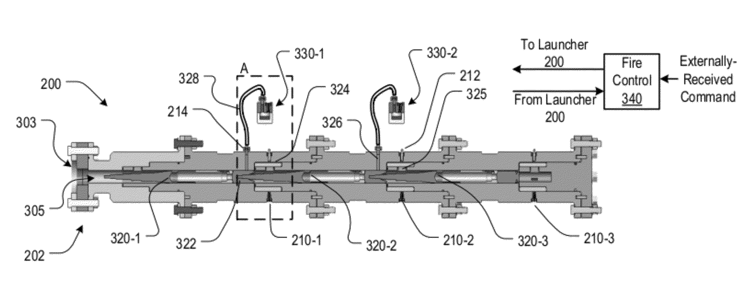
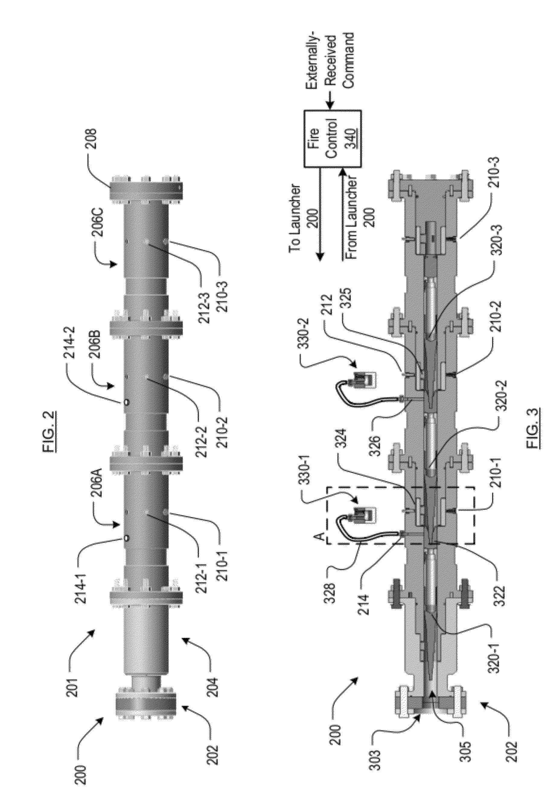
[0013]To that end, and in accordance with the illustrative embodiment, external propellant bays are disposed outside of the launcher, but are placed in fluidic communication with bore of the barrel through a pressure relief system and several conduits / channels. Each external propellant bay includes propellant that, when ignited, generates a gas. The gas, which is conveyed to the bore of the barrel, raises the pressure in the bore to a level sufficient to expel water therefrom. This provides a brief window of time in which a projectile can be launched.
[0015]When exposed to the pressure in the high-pressure conduit, the second pressure relief device relieves pressure, permitting the gas in the high-pressure conduit to flow (via the channel) to the bore of the launcher. As a consequence, the pressure in the bore rapidly rises to a level that is sufficient to expel water. In the illustrative embodiment, the second pressure relief device is a rupture disc. During launch of a projectile, the second pressure-relief device holds pressure and thereby prevents propellant gas (that is generated during launch of a projectile) from entering the high pressure conduit and it also prevents water that enters bore (after the launch of a projectile) from entering the high pressure conduit.

Problems solved by technology

A gun, especially one that fires a projectile at a high muzzle velocity, cannot be fired when water is in its barrel.
If a firing where to incur in a water-filled barrel, a very high breach pressure would result as the ignited propellant charge forces (or tries to force) the water out of the barrel.
The likely result would be material failure of the barrel.
But in the context of an underwater weapon having a high muzzle-velocity, most prior-art solutions solve one problem—clearing the barrel of water—only to create other problems.
The application of this solution to an underwater gun that fires stacked, “supercavitating” rounds is problematic.

Method used


Image

  • Multi-shot Launcher Comprising External Propellant
  • Multi-shot Launcher Comprising External Propellant
  • Multi-shot Launcher Comprising External Propellant

Examples


Embodiment Construction

[0037]The terms appearing below are defined for use in this disclosure and the appended claims as follows:[0038]“Operatively Coupled” means that a first object, which might be remote from a second object, can have some effect on the second object or have some effect on a third object through the second object, etc. For example, consider a rigid linkage having a first end and a second end. The first end attaches to a plate and the second end abuts a wall. The linkage is capable of transferring, to the wall, a force that is received at the plate. The linkage and the plate can therefore be considered to be operatively coupled for transmitting a force. Operatively-coupled objects need not be in direct contact with one another and, as appropriate, can be coupled through any medium (e.g., semiconductor, air, vacuum, water, copper, optical fiber, etc.). The coupling between operatively-coupled objects can transmit, as appropriate for the nature of the coupling and the objects, any type of ...


PUM


Abstract

An underwater gun for firing stacked munitions includes external propellant bays. In some embodiments, after a first munition is launched from the barrel of the launcher, propellant in one of the external propellant bays is ignited. The gas that is generated upon ignition is routed to the bore of the barrel and expels water that is in the barrel. A munition is then immediately launched through the cleared barrel.

Description

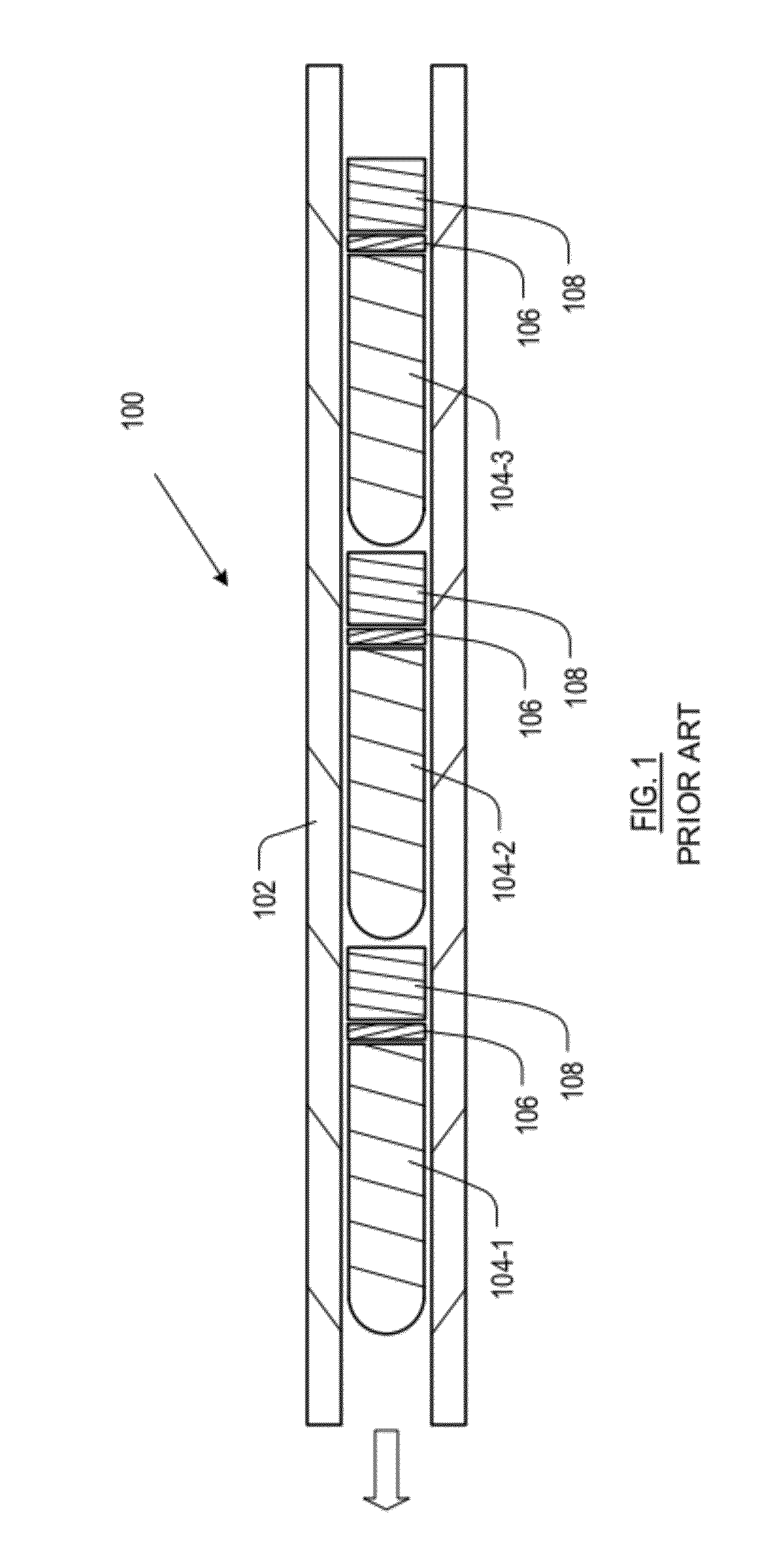
STATEMENT REGARDING FEDERALLY-SPONSORED RESEARCH[0001]This invention was made with Government support under N00014-07-C-1103 awarded by the U.S. Navy. The Government has certain rights in the invention.FIELD OF THE INVENTION[0002]The present invention relates to munitions in general, and, more particularly, to weapons capable of launching multiple stacked projectiles underwater.BACKGROUND OF THE INVENTION[0003]FIG. 1 depicts a partial, simplified view of barrel 102 of multi-shot grenade launcher 100. In launcher 100, three grenades 104-1, 104-2, and 104-3 are “stacked” one behind another in barrel 102. Grenade 104-1 is in position 1 (i.e., first to be launched), grenade 104-2 is in position 2 and grenade 104-3 is in position 3 as the third grenade to be launched. This “stacked” grenade launcher technology is available from Metal Storm Inc. as the “3GL” 3-shot semi automatic modular grenade launcher.[0004]Attached to the aft end of each grenade is propulsion base 108. The propulsion ...

Claims


Application Information

Patent Timeline
Patent Type & Authority Applications(United States)
IPC IPC(8): F41F1/00
CPCF41C9/06F42B5/035F41F1/00
Inventor PAULIC, ANTONIO
Owner LOCKHEED MARTIN CORP
Learn More