Method for the slip regulation of a friction clutch and clutch actuator therefor

a technology of friction clutch and actuator, which is applied in the direction of fluid clutch, non-mechanical actuated clutch, magnetically actuated clutch, etc., can solve the problems of increased wear-inducing heat entering the friction clutch, small rotational angle of the rotor, and high fuel consumption, so as to reduce the risk of wear and the effect of high axial travel

Inactive Publication Date: 2012-08-23
SCHAEFFLER TECH AG & CO KG
View PDF6 Cites 7 Cited by
  • Summary
  • Abstract
  • Description
  • Claims
  • Application Information

AI Technical Summary

Benefits of technology

[0005]The present invention provides a method for controlling a clutch actuator and a clutch actuator that have a relatively high resolution of axial travel in order to be able to economically control a friction clutch and in a way which is less susceptible to wear.
[0007]It has become apparent that the sensors per se do not exhibit any digital behavior, but rather the sensor signal exhibits sinusoidal behavior if a magnet element which rotates with the rotor is moved past the Hall sensor. Accordingly, through the evaluation of these analog signal lines by a plurality of Hall sensors arranged over the circumference, it is possible for an analog signal which is continuous over one rotation of the rotor to be determined by virtue of the fact that the individual signals of the Hall sensors are evaluated. In particular, by comparing the signals of two Hall sensors which are adjacent in the circumferential direction it is possible for each angle of the rotor between two Hall sensors to be resolved in the scope of the resolution of the analog signal. As a result, given the same number of Hall sensors the resolution increases to such an extent that digitized behavior of the rotor is no longer observed and / or the number of Hall sensors can be reduced, with the result that expenditure on the determination of the rotational speed of the rotor can be reduced.
[0008]The increased resolution of the angular position of the rotor allows the latter to be set precisely to various positions between the angular positions of the Hall sensors and secured. In this way, the axial resolution of the axial travel also increases, with the result that the slip at the friction clutch is controlled more accurately and can be secured to a low differential rotational speed between a friction clutch and clutch disk. It has become apparent that given an average regulation frequency of one hertz, that is to say one regulation impulse per second, differential rotational speeds of less than 12 rpm can be set. This permits the friction clutch to be operated with relatively little feeding in of heat, and therefore allows fuel to be saved owing to the reduced feeding in of heat.
[0009]By virtue of the sensing of the sinusoidal signals of the Hall sensors over the rotational angle of the rotor it is possible for the windings of the electric motor to be commutated in sinusoidal fashion in accordance with the sinusoidal signals of the associated Hall sensor, instead of block wise commutation of the electric motor during which one phase or winding of an electric motor is commutated as a function of the associated signal of the Hall sensor, Which is digital and therefore incremental over the rotational angle of the rotor, with a predefined constant excitation current or an associated excitation voltage, for example in the form of a voltage which is input over a predefined pulse width. This means that a sinusoidal excitation current or a correspondingly sinusoidal excitation voltage is impressed on the windings over a predefined rotational. angle. According to one advantageous exemplary embodiment, in this context the magnetizable magnet segments are energized in an analog fashion as windings of different phases of the electric motor as a function of an analog control variable which is determined from the analog signals of the Hall sensors. Analog energization means, in contrast to digital control, no time-consuming switching on and switching off processes. In this context, for the purpose of analog energization, components of power electronics, for example continuously connected or controlled transistors, can be used in the same way.
[0010]According to the inventive method, in this context not only the commutation of the magnetizable magnet segments is provided as a function of an analog evaluation of the Hall sensors in order to secure the rotor, for example, in an angular position between two Hall sensors. Instead, it is possible to determine, as it were, in an analog fashion the axial travel of the clutch actuator from the analog signals of the Hall sensors taking, into account the transmission ratio of a gear mechanism for converting the rotational movement of the electric motor into said axial travel of the clutch actuator. The regulation of the axial travel can he carried out with improved resolution on the basis of this axial travel.

Problems solved by technology

The axial travel of the friction clutch and therefore, the clutch actuator for regulating the slip rotational speed is very low here, with the result that correspondingly small rotational angles of the rotor are necessary.
In this way, slip control is possible only with a comparatively large control width and therefore increased slip rotational speeds, which leads to increased wear-inducing feeding of heat into the friction clutch and therefore to a higher consumption of fuel.

Method used


Image

  • Method for the slip regulation of a friction clutch and clutch actuator therefor
  • Method for the slip regulation of a friction clutch and clutch actuator therefor

Examples


Embodiment Construction

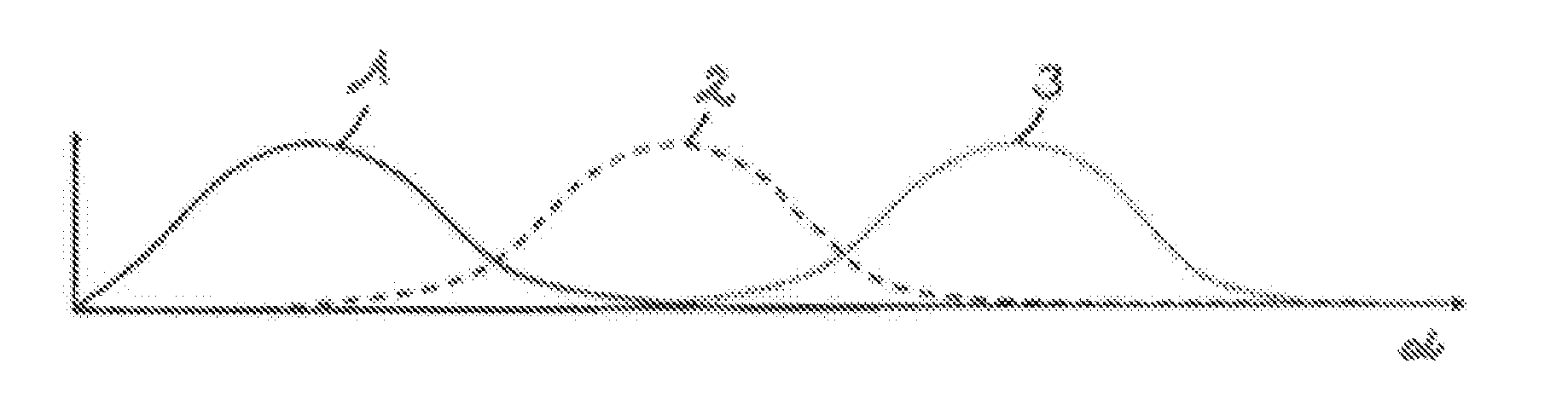
[0015]FIG. 1 shows the signal profiles 1, 2, 3, sensed in analog fashion, of three Hall sensors arranged uniformly one next to the other in the circumferential direction of the rotor, over the rotational angle α of the rotor of an electric motor. The signal profiles 1, 2, 3 are sinusoidal and overlap one another, in such a way that the signals of two Hall sensors are available to each rotational angle α of the rotor, and can be determined discretely and with high resolution by means of the information as to which sensors are involved with which signal component. The invention is not restricted by the fact that the signal profiles 1, 2, 3 which occur in analog fashion in the sensors are digitized in a signal processing step in a sensor in-situ electronics system or in a control unit, for example by means of an A / D converter.

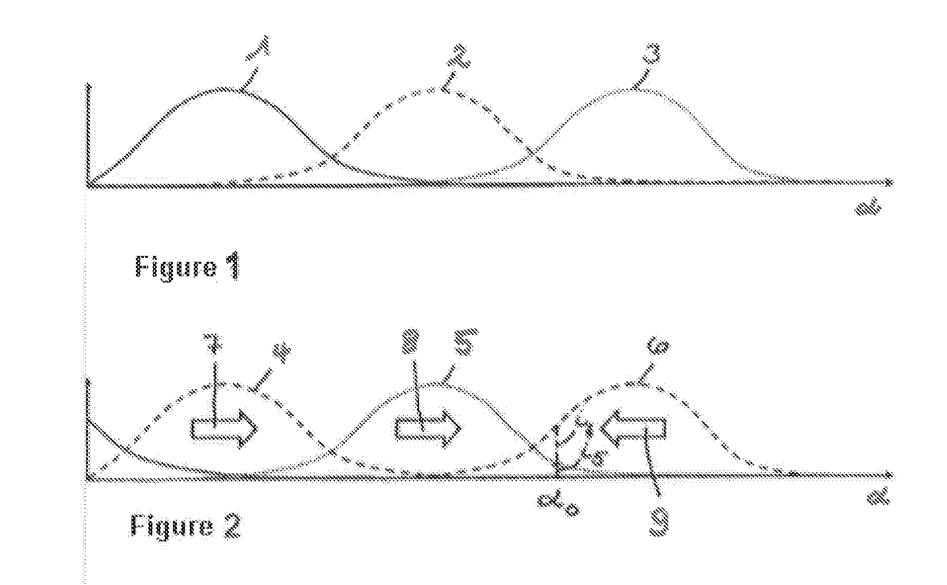
[0016]FIG. 2 shows the commutation, occurring on the basis of the signal profiles 1, 2, 3 of FIG. 1, of the magnetizable magnet elements such as windings or coils...


PUM


Abstract

A method for slip regulation of a friction clutch by a clutch actuator operated by an electronically commutated electric motor, Here, rotational motion of a rotor is converted into an axial advancement that sets a predetermined slip. The rotational motion is controlled by Hall sensors arranged over a circumference around a rotational axis of the rotor. Magnetizable magnet segments, which are offset from each other in the circumferential direction, communicate depending on continuously detected signals of the Hall sensors, To perform the slip regulation even for axial travels of the clutch actuator that correspond to an angular position of the rotor between two Hall sensors, the signals of the Hall sensors over the circumference are evaluated in an analog manner, and an angular position of the rotor between two sensors is determined by comparing two signals adjacent to each other in the circumferential direction with each other.

Description

CROSS-REFERENCE TO RELATED APPLICATIONS[0001]This application is a continuation of PCT / DE2010 / 001216 filed Oct. 14, 2010, which in turn claims the priority of DE 10 2009 052 515.7 filed Nov. 9, 2009. The priority of these applications is hereby claimed and these applications are incorporated by reference hereinFIELD OF THE INVENTION[0002]The invention relates to a method for the slip regulation of a friction clutch by a clutch actuator operated by an electronically commutated electric motor.BACKGROUND OF THE INVENTION[0003]DE 103 23 567 A1 discloses a method and device for controlling the slip of a friction clutch. In this context, a clutch actuator is controlled by a control device in such a way that a predefined slip between the friction clutch, which is mounted on the crank shaft of an internal combustion engine and a clutch disk, which bears friction linings and is connected to the gear mechanism input shaft of a gear mechanism is set on the friction clutch, in order to reduce o...

Claims


Application Information

Patent Timeline
Patent Type & Authority Applications(United States)
IPC IPC(8): F16D19/00
CPCF16D48/064F16D2300/18F16D2500/5012F16D2500/3021F16D2500/1023
Inventor GOEPPERT, GEORG
Owner SCHAEFFLER TECH AG & CO KG
Why Eureka
Try Eureka