Eureka AIR delivers breakthrough ideas for toughest innovation challenges, trusted by R&D personnel around the world.

Energy conversion systems and methods

a technology of energy conversion system and energy conversion method, which is applied in the direction of electric generator control, final product manufacturing, machines/engines, etc., can solve the problems of displacement of one or more components, tidal power is reliably predictable, and energy conversion system can pose challenges

Active Publication Date: 2012-08-23
OCEANA ENERGY
View PDF37 Cites 68 Cited by
  • Summary
  • Abstract
  • Description
  • Claims
  • Application Information

AI Technical Summary

Benefits of technology

[0014]It is to be understood that both the foregoing general description and the following detailed description are exemplary and explanatory only and are not restrictive of the inven

Problems solved by technology

Unlike other renewable energy sources, such as wind and solar power, however, tidal power is reliably predictable.
Energy conversion systems can pose challenges relating to the stress and / or strain on the various components of such systems resulting from the interaction of the relatively strong forces associated with fluid flow (e.g., moving currents).
For example, as a fluid current (e.g., tidal current) interacts with an energy conversion system, there is an amount of thrust that acts on the various components, which may cause displacement of one or more components, particularly components configured to move relative to stationary components.
Additional challenges may arise from such energy conversion systems' reliance on relative rotational movement of components to produce energy.
For example, friction and / or drag associated with rotational movement of such systems may hinder efficiency of the system.
Moreover, such relative motion can, for example, cause wear of such components, which may be exacerbated when an energy conversion systems is placed underwater, for example, in a sea or other body of water containing relatively harsh, deteriorative substances (e.g., salt).

Method used


Image

  • Energy conversion systems and methods
  • Energy conversion systems and methods
  • Energy conversion systems and methods

Examples


Embodiment Construction

[0031]Reference will now be made in detail to various exemplary embodiments of the present teachings, examples of which are illustrated in the accompanying drawings. Wherever possible, the same reference numbers will be used throughout the drawings to refer to the same or like parts.

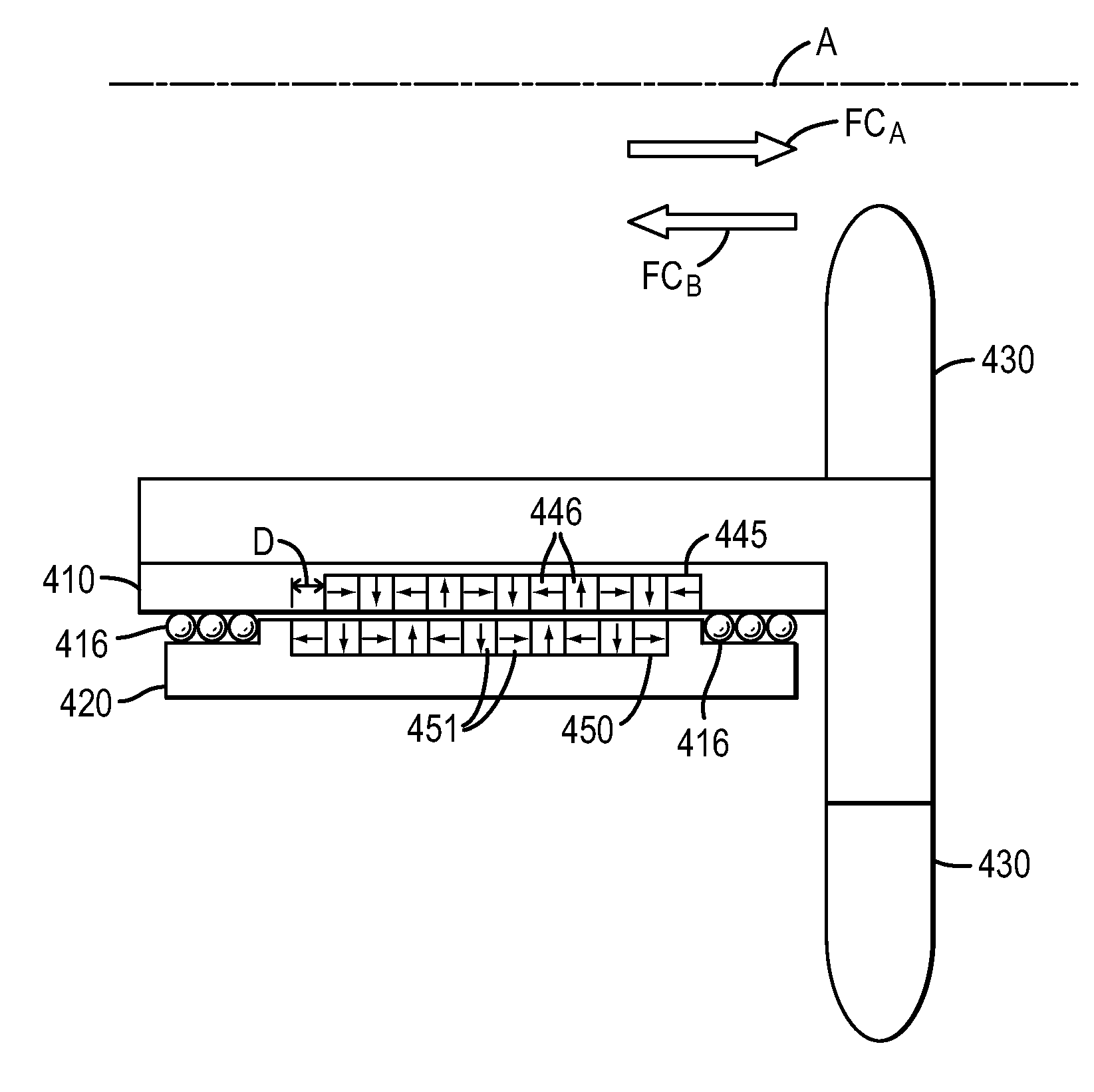
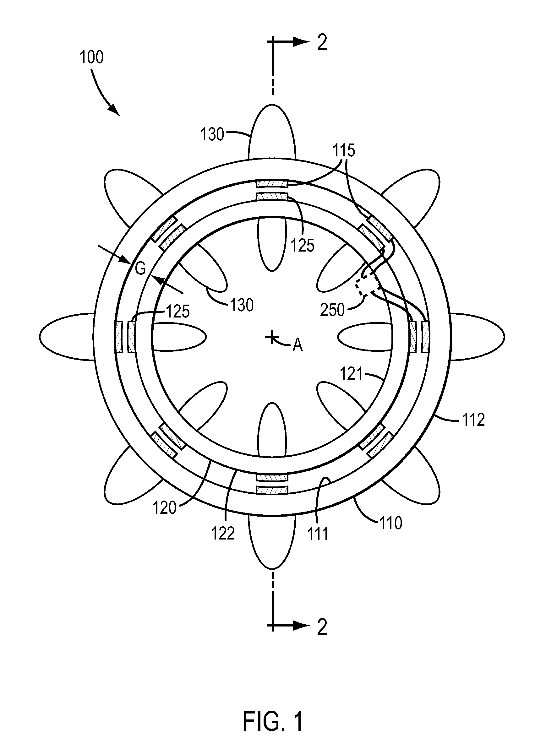
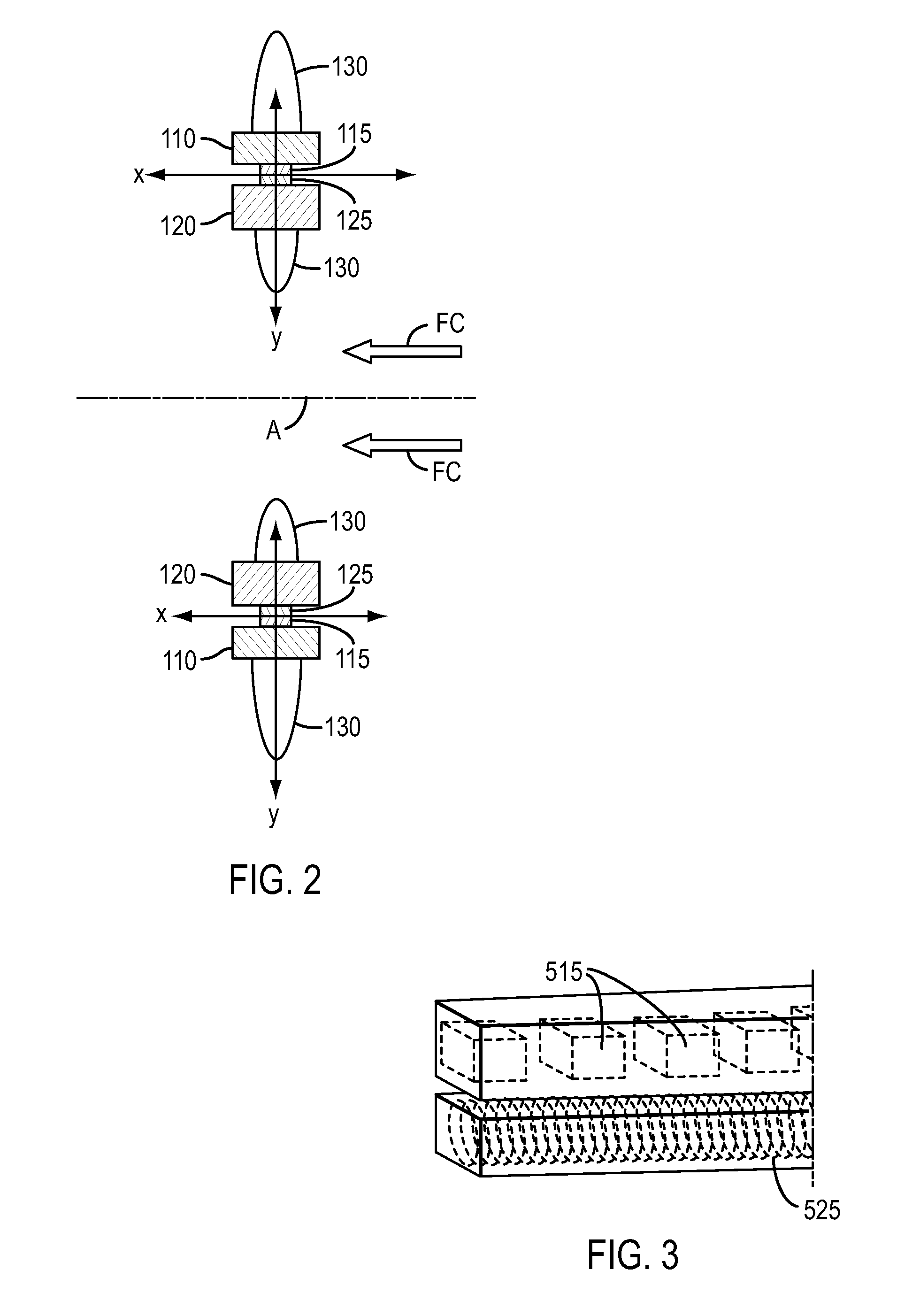
[0032]Various exemplary embodiments of the present teachings contemplate an energy conversion system configured to interact with fluid streams, such as, for example, tidal currents, that utilizes an open-center configuration and relative movement of components of the system to convert kinetic energy from fluid flow into other useful forms of energy, such as, for example, electricity and / or hydrogen production. In various exemplary embodiments, the present teachings contemplate one or more blade members supported by and extending radially outwardly and / or inwardly from a rotatable structure that is rotatably mounted relative to a stationary structure. Fluid flowing past the system may interact with the bl...


PUM


Abstract

An energy conversion system may include a stationary structure, a rotatable structure configured to rotate relative to the stationary structure, wherein the rotatable structure defines an axis of rotation. The system may further include at least one blade member mounted to and extending radially outward from the rotatable structure, the at least one blade member being configured to interact with fluid currents flowing in a direction substantially parallel to the axis of rotation to cause the rotatable structure to rotate about the axis of rotation, and at least one bearing mechanism disposed to provide at least one of a radial and axial bearing between the rotatable structure and the stationary structure as the rotatable structure rotates about the stationary structure. The system may be configured to convert rotation of the rotatable structure to at least one of electricity and hydrogen production.

Description

[0001]This application claims the benefit of U.S. Provisional Application No. 61 / 256,009, filed Oct. 29, 2009, and U.S. Provisional Application No. 61 / 325,563, filed Apr. 19, 2010, which are incorporated by reference herein in their entirety.TECHNICAL FIELD[0002]The present teachings relate generally to energy conversion systems that convert the kinetic energy from fluid flow, such as, for example, from liquid currents, to another form of energy, such as, for example, electricity and / or hydrogen production.INTRODUCTION[0003]The section headings used herein are for organizational purposes only and are not to be construed as limiting the subject matter described in any way.[0004]Electricity generation using systems that convert energy from fluid currents, for example, wind or water currents, is well known. Tidal power exploits the movement of water caused by tidal currents, or the rise and fall in sea levels due to tides. As the waters rise and then fall, a flow, or current, is genera...

Claims


Application Information

Patent Timeline
IPC IPC(8): F03B13/00
CPCF03B13/264F05B2220/61F05B2220/706F05B2240/511F05B2240/52F16C2360/31F16C32/0423H02K7/09H02K7/1823Y02E10/28Y02E70/10F05B2240/54F16C32/0402F16C32/0408F16C39/063F16C2300/14F16C2360/00Y02E10/30Y02E60/36Y02P70/50Y02E10/20F03B13/10F03B13/26F03B15/00F16C32/0417H02K7/1853
Inventor DAVEY, KENTHANSEN, NED R.POWER, III, DANIEL E.
Owner OCEANA ENERGY
Why Eureka
Eureka Blog
Learn More