Global offset compensation for a CNC machine

a global offset compensation and cnc machine technology, applied in process control, process control, instruments, etc., can solve problems such as inability to perfectly align, inconvenient maintenance, linear and rotational position errors of tables,

Active Publication Date: 2012-08-23
GM GLOBAL TECH OPERATIONS LLC
View PDF11 Cites 17 Cited by
  • Summary
  • Abstract
  • Description
  • Claims
  • Application Information

AI Technical Summary

Benefits of technology

[0004]A method for loading a part on a four-axis CNC machine having six degrees of freedom comprises mounting a fixture on a table for the CNC machine and clamping a part to the fixture. A plurality of features and surfaces are machined on the part and an actual part center position is determined using the machined features and surfaces. A table offset, a fixture offset, and a rotary axis offset of the actual part center position to a nominal part center position are calculated. The table and the fixture are translated by the table offset, the fixture offset, and the rotary axis offset. A controller is programmed with a global offset compensation based upon the calculated offset amount for each of the six degrees of freedom to translate the coordinate system on each of the four axes to the actual part center position.
[0005]A method for loading a part on a five-axis CNC machine having nine degree of freedom comprises mounting a fixture on a table for the CNC machine and clamping a part to the fixture. A plurality of features and surfaces are machined on the part and an actual part center position is determined using the machined features and surfaces. A first table offset, a second table offset, a fixture offset, a first rotary axis offset, and a second rotary axis offset of the actual part center position to a nominal part center position are calculated. The tables and the fixture are translated by the first table offset, the second table offset, the fixture offset, the first rotary axis offset, and the second rotary axis offset. A controller is programmed with a global offset compensation based upon the calculated offset amount for each of the nine degrees of freedom to translate the coordinate system on each of the five axes to the actual part center position.

Problems solved by technology

When the part is clamped on the fixture during machining, it is possible that it is distorted by clamping pressure and / or tool pressure and endure also will not be perfectly aligned with the fixture, due to debris or other locating errors.
Additionally, the tables have linear and rotational position errors.
This time consuming method requires the effort of skilled maintenance personnel to indicate the tables and adjust the parameters.
However, residual errors remain even after the maintenance procedure is performed and over time the table positions may drift, increasing table position errors.
The fixture may also have alignment errors.
However, both table errors and fixture errors affect the part quality.

Method used


Image

  • Global offset compensation for a CNC machine
  • Global offset compensation for a CNC machine
  • Global offset compensation for a CNC machine

Examples


second embodiment

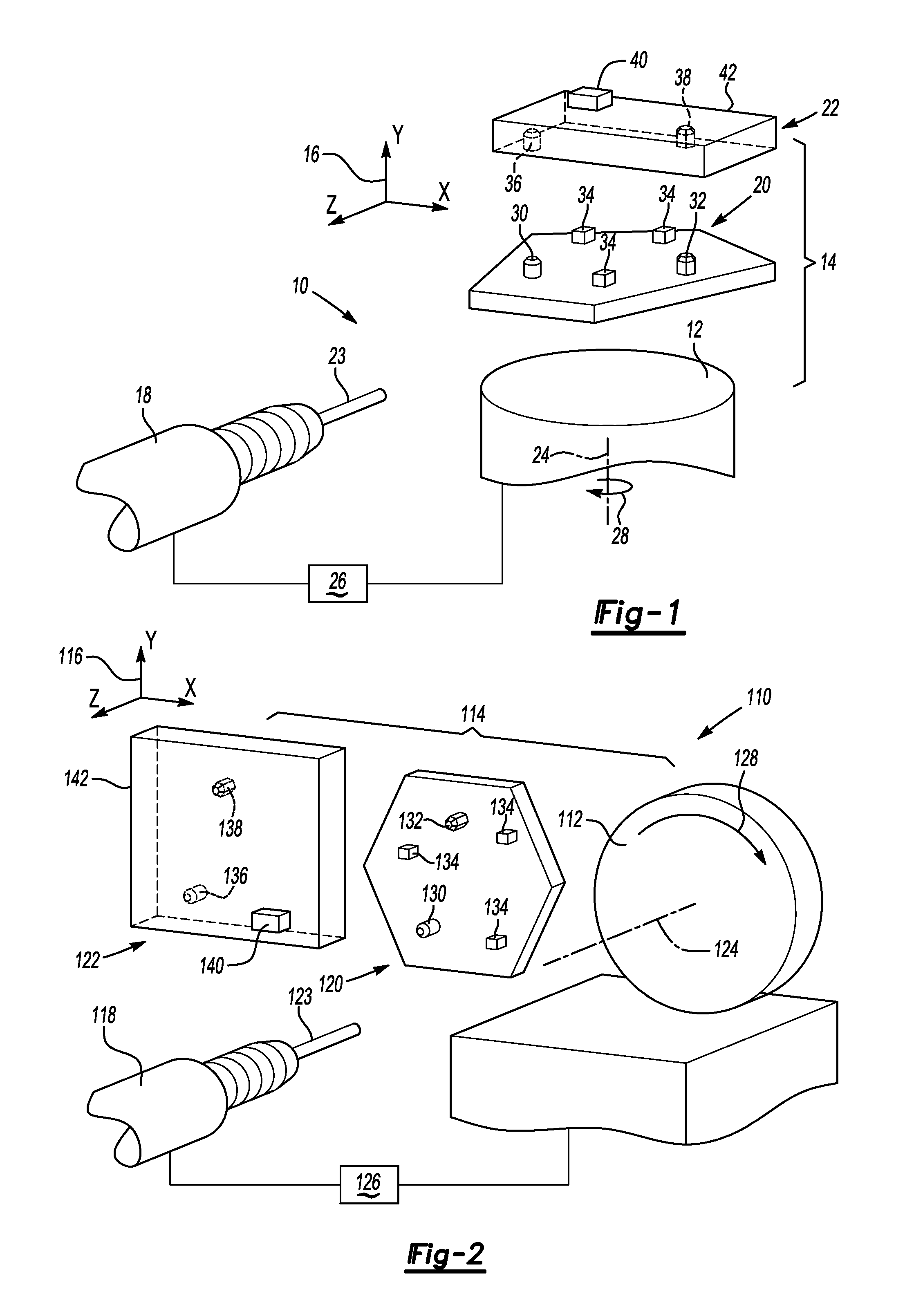
[0029]FIG. 2 illustrates a partial view of a portion of a CNC machine 110. In particular, the CNC machine is a four-axis C rotary table CNC machine 110. The CNC machine 110 has a table 112. The embodiment in FIG. 2 differs from the embodiment of FIG. 1 in that the CNC machine is a C rotary table rather than a B rotary table and the global offset compensation for the table will accordingly be different as explained below.

[0030]A fixture 120 and a part 122 may be assembled on the table 112, as illustrated at 114. A coordinate system 116 is associated with the table 112. A spindle 118 is operatively connected to the CNC machine 110 and can be adjusted by the coordinate system 116 for the CNC machine 110. The spindle 118 is oriented along the Z-axis of the coordinate system 116. A cutting tool 123 is clamped on the spindle 118 for machining the part 122.

[0031]The spindle 118 and the table 112 are operatively connected to a controller 126 to provide input from the spindle 118 and the tab...

third embodiment

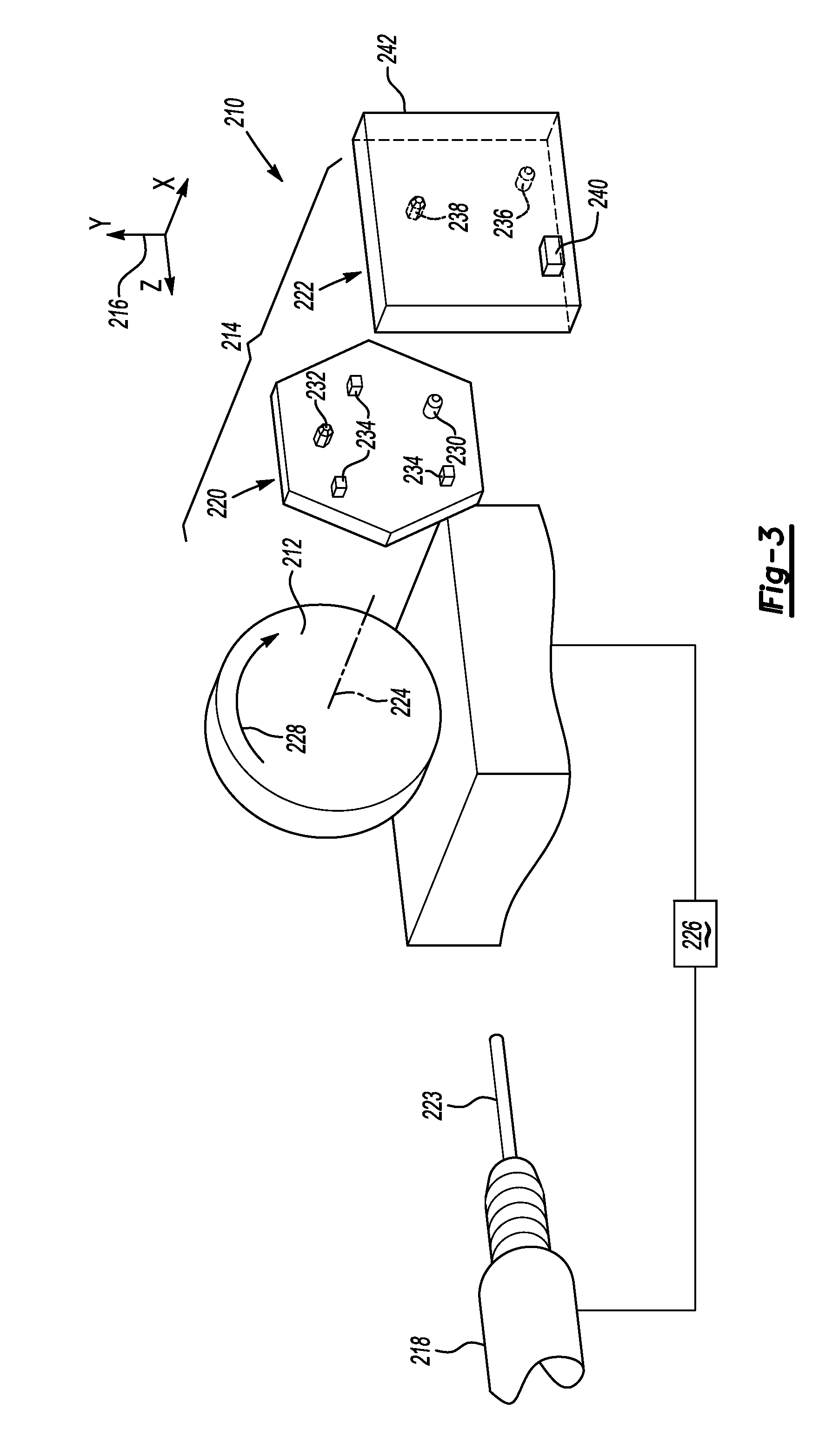
[0040]FIG. 3 illustrates a partial view of a portion of a CNC machine 210. The CNC machine 210 is a four-axis A rotary table CNC machine 210. The CNC machine 210 has a table 212. The embodiment in FIG. 3 differs from the embodiments above in that the CNC machine is an A rotary table rather than a B or a C rotary table and the global offset compensation for the table will accordingly be different as explained below.

[0041]A fixture 220 and a part 222 may be assembled on the table 212, as illustrated at 214. A coordinate system 216 is associated with the table 212. A spindle 218 is operatively connected to the CNC machine 210 and can be adjusted by the coordinated system 216 for the CNC machine 210. The spindle 218 is oriented along the Z-axis of the coordinate system 216. A cutting tool 223 is clamped on the spindle 218 for machining the part 222. The cutting edge of the cutting tool 223 can remove material from the part 222. The machine part 222 is measured by a CMM machine (not show...

fourth embodiment

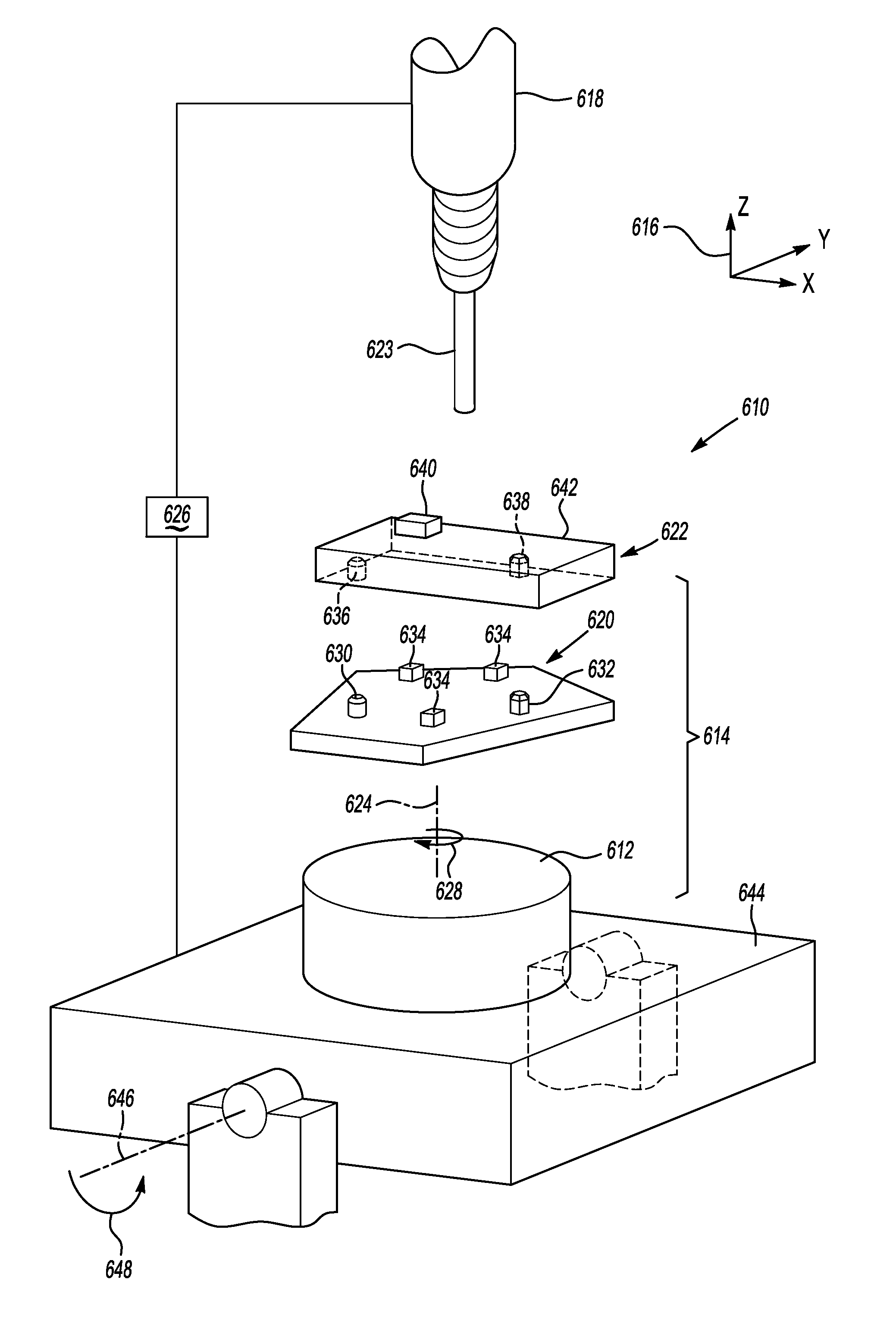
[0051]FIG. 4 illustrates a partial view of a portion of a CNC machine 310. The CNC machine is a five-axis A-on-B rotary table CNC machine 310. The CNC machine 310 has a first or A-table 312 which is installed on a second or B-table 344. The embodiment in FIG. 4 differs from the embodiment above in that the CNC machine 310 is a five-axis machine rather than a four-axis machine and the global offset compensation for the table will accordingly be different as explained below. The A-table 312 rotates about the A-axis (shown at 324) and the B-table 344 rotates about the B-axis (shown at 346). The rotation of the A-table 312 is represented by arrow 328 and by arrow 348 for the B-table 344.

[0052]A fixture 320 and a part 322 may be assembled on the A-table 312, as illustrated at 314. A coordinate system 316 is associated with the CNC machine 310. A spindle 318 is operatively connected to the CNC machine 310. The movements of the spindle 318 can be adjusted by the coordinate system 316 for t...


PUM

PropertyMeasurementUnit
degrees of freedomaaaaaaaaaa
degree of freedomaaaaaaaaaa
degrees of freedomaaaaaaaaaa

Abstract

A method for offsetting a part on a CNC machine comprises clamping a part to a fixture on a table for the CNC machine and machining a plurality of features and surfaces on the part. A plurality of global offsets are calculated for the fixture and the table based on location data of the plurality of features and surfaces. An actual part position on a global coordinate system for the CNC machine is determined by translating the fixture and the table by each the plurality of global offsets to the coordinate system. The actual part position is compensated to a nominal part position for each of the controllable axes of the CNC machine and a controller is programmed with a global offset compensation based upon the calculated offset for each controllable axis of the CNC machine to adjust each of the controllable axes to the actual part position.

Description

TECHNICAL FIELD[0001]The present invention relates generally to properly offsetting parts for machining on a CNC machine.BACKGROUND[0002]Computed numerically controlled (CNC) machines are frequently used to manufacture items that require machining processes to be used. In order to maximize CNC machining productivity, fixtures may be employed to hold the part in place during machining The fixtures are aligned with the machine table. A fixture allows parts with different locating and clamping arrangements to be machined on a common machine table. When the part is clamped on the fixture during machining, it is possible that it is distorted by clamping pressure and / or tool pressure and endure also will not be perfectly aligned with the fixture, due to debris or other locating errors. Additionally, the tables have linear and rotational position errors. A complex maintenance procedure for correcting the table error is currently used. This time consuming method requires the effort of skill...

Claims


Application Information

Patent Timeline
Patent Type & Authority Applications(United States)
IPC IPC(8): B23Q11/00
CPCG05B2219/42132G05B2219/50297G05B19/402Y10T82/2502Y10T409/303752
Inventor GU, JIEKURGIN, SHERI K.
Owner GM GLOBAL TECH OPERATIONS LLC
Why Eureka
Try Eureka