Porous implant structures

a technology of porous implants and implants, applied in the field of porous implants, can solve the problems of insufficient strength to serve as weight-bearing structures in many medical implants, formation of undesirable metal compounds in metal foam, and the conventional metal foam fabrication process consumes substantial amounts of energy, so as to improve strength and porosity

Inactive Publication Date: 2012-08-23
SMITH & NEPHEW INC
View PDF11 Cites 184 Cited by
  • Summary
  • Abstract
  • Description
  • Claims
  • Application Information

AI Technical Summary

Benefits of technology

[0012]One objective of the invention is to provide porous biocompatible structures suitable for use as medical implants that have improved strength and porosity.
[0013]Another objective of the invention is to provide methods to fabricate porous biocompatible structures suitable for use as medical implants that have improved strength and porosity.

Problems solved by technology

While metal foams formed by such conventional methods provide good porosity, they may not provide sufficient strength to serve as weight bearing structures in many medical implants.
Further, the processes used to form metal foams may lead to the formation of undesirable metal compounds in the metal foams by the reaction between the metal and the PFA.
Conventional metal foam fabrication processes also consume substantial amounts of energy and may produce noxious fumes.
While DMF can be used to provide dense structures strong enough to serve as weight bearing structures in medical implants, such structures do not have enough porosity to promote tissue and bone in-growth.
Conversely, DMF can be used to provide porous structures having enough porosity to promote tissue and bone in-growth, but such porous structures lack the strength needed to serve as weight bearing structures.
Other laser RMT techniques are similarly deficient for orthopedic implants requiring strength, porosity and connectivity.

Method used


Image

  • Porous implant structures
  • Porous implant structures
  • Porous implant structures

Examples


Embodiment Construction

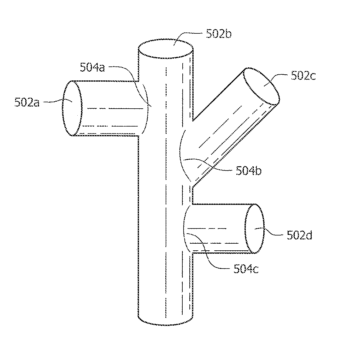
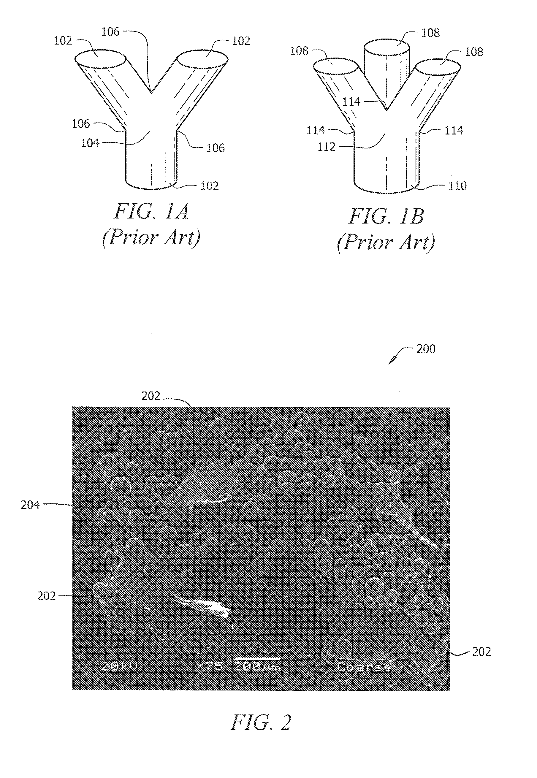
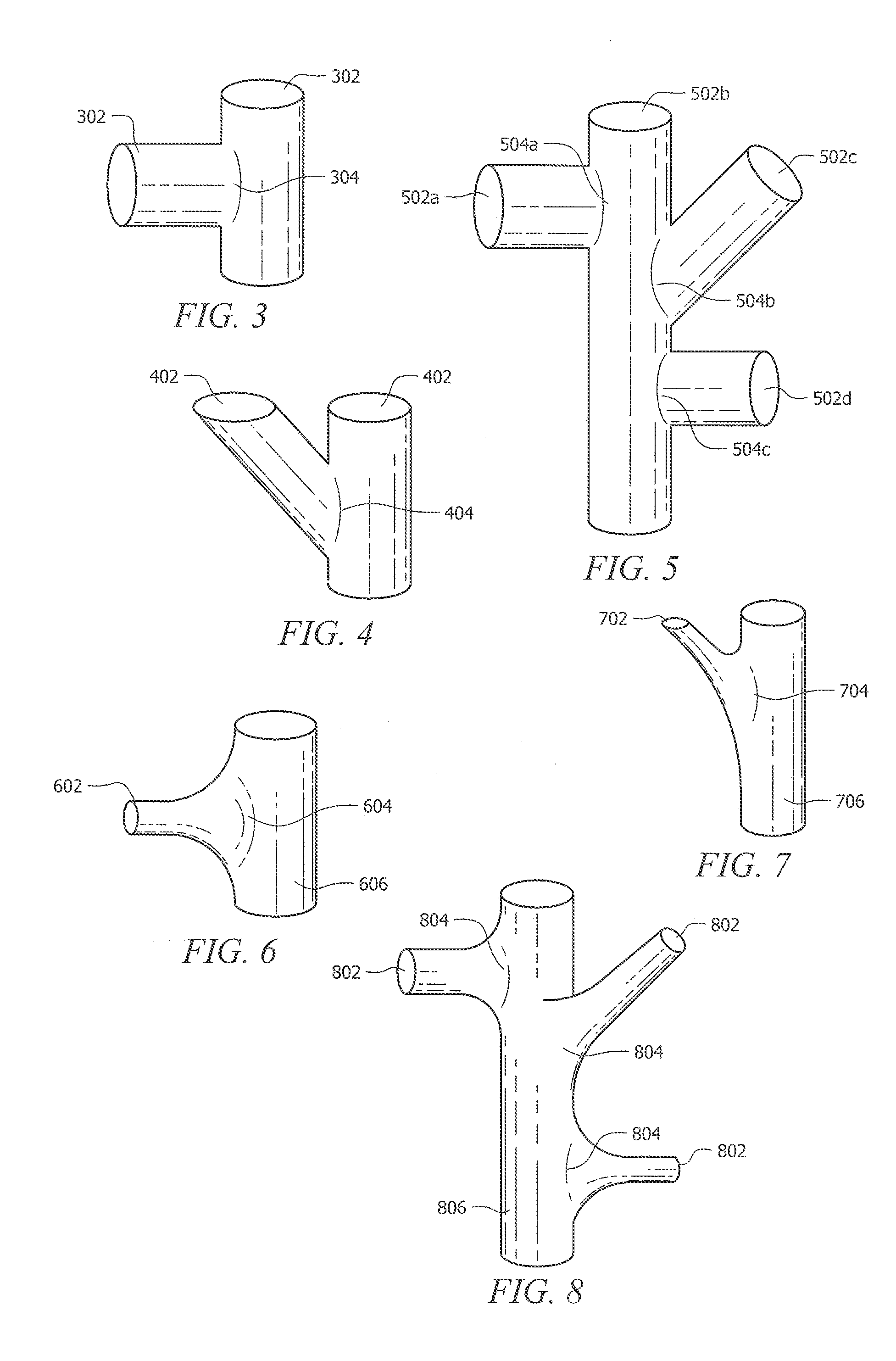
[0086]As discussed above, Rapid Manufacturing Techniques (RMT) such as Direct Metal Fabrication (DMF) can be used to produce porous structures for medical implants. However, using DMF or other RMT to fabricate porous structures can create weak areas between fenestrations of the three-dimensional porous structure. This is mostly due to the shapes and configurations of the cells that have been used in the prior art to form these porous structures. In particular, fractures typically occur at areas where struts are connected together at a node. The fractures occur in porous structures of the prior art because the cross-sectional area of a strut where it connects to the node is typically less than the cross-sectional area of the resulting node. The areas where the struts connect to their node, typically referred to as stress risers, are common points of structural failure. The pattern of failure at the stress risers can also occur when the molten phase of particles does not completely me...


PUM

PropertyMeasurementUnit
porositiesaaaaaaaaaa
structureaaaaaaaaaa

Abstract

Porous biocompatible structures suitable for use as medical implants and methods for fabricating such structures are disclosed. The disclosed structures may be fabricated using rapid manufacturing techniques. The disclosed porous structures has a plurality of struts and nodes where no more than two struts intersect one another to form a node. Further, the nodes can be straight, curved, portions that are curved and / or straight. The struts and nodes can form cells which can be fused or sintered to at least one other cell to form a continuous reticulated structure for improved strength while providing the porosity needed for tissue and cell in-growth.

Description

[0001]The present application claims the benefit of U.S. Provisional Patent Application No. 61 / 235,269, filed Aug. 19, 2009 and entitled “Porous Implant Structures,” the disclosure of which is incorporated by reference herein in its entirety.FIELD OF INVENTION[0002]The present invention generally relates to porous structures suitable for medical implants, and more particularly to porous structures suitable for medical implants that have improved combinations of strength, porosity and connectivity and methods for fabricating such improved porous structures.BACKGROUND[0003]Metal foam structures are porous, three-dimensional structures with a variety of uses, including medical implants. Metal foam structures are suitable for medical implants, particularly orthopedic implants, because they have the requisite strength for weight bearing purposes as well as the porosity to encourage bone / tissue in-growth. For example, many orthopedic implants include porous sections that provide a scaffol...

Claims


Application Information

Patent Timeline
Patent Type & Authority Applications(United States)
IPC IPC(8): A61F2/02B23P11/00
CPCA61F2/28A61F2002/3028A61F2002/30914Y10T29/49826A61F2002/30962A61F2230/0063A61L27/56A61F2002/3092B33Y10/00B33Y80/00B33Y70/00B33Y70/10A61L27/06A61L27/42A61L24/0036A61F2002/30593
Inventor SHARP, JEFFREYJANI, SHILESH C.GILMOUR, LAURA J.LANDON, RYAN L.
Owner SMITH & NEPHEW INC
Why Eureka
Try Eureka