
Tool path generation method and device

a tool path and tool technology, applied in the direction of electric programme control, program control, instruments, etc., can solve the problem of changing the path of the tool

Inactive Publication Date: 2012-08-23
MAKINO MILLING MASCH CO LTD
View PDF21 Cites 21 Cited by
  • Summary
  • Abstract
  • Description
  • Claims
  • Application Information

AI Technical Summary

Benefits of technology

The present invention provides a tool path generation method and device for machining a workpiece with a machine tool. The method includes reading the tool path from the machining program, setting target points on the tool path at equal intervals, calculating an approximation curve or average coordinates of adjacent target points, and generating the tool path based on the approximation curve or average coordinates. This method ensures that the same tool path is generated if the original tool path is the same, resulting in a smooth machined surface without step differences between adjacent tool paths.

Problems solved by technology

The method disclosed in Patent Literature 1 has the problem that, even if the original tool path is the same, a tool path ends up changing due to the adjacent paths.

Method used


Image

  • Tool path generation method and device
  • Tool path generation method and device
  • Tool path generation method and device

Examples


Embodiment Construction

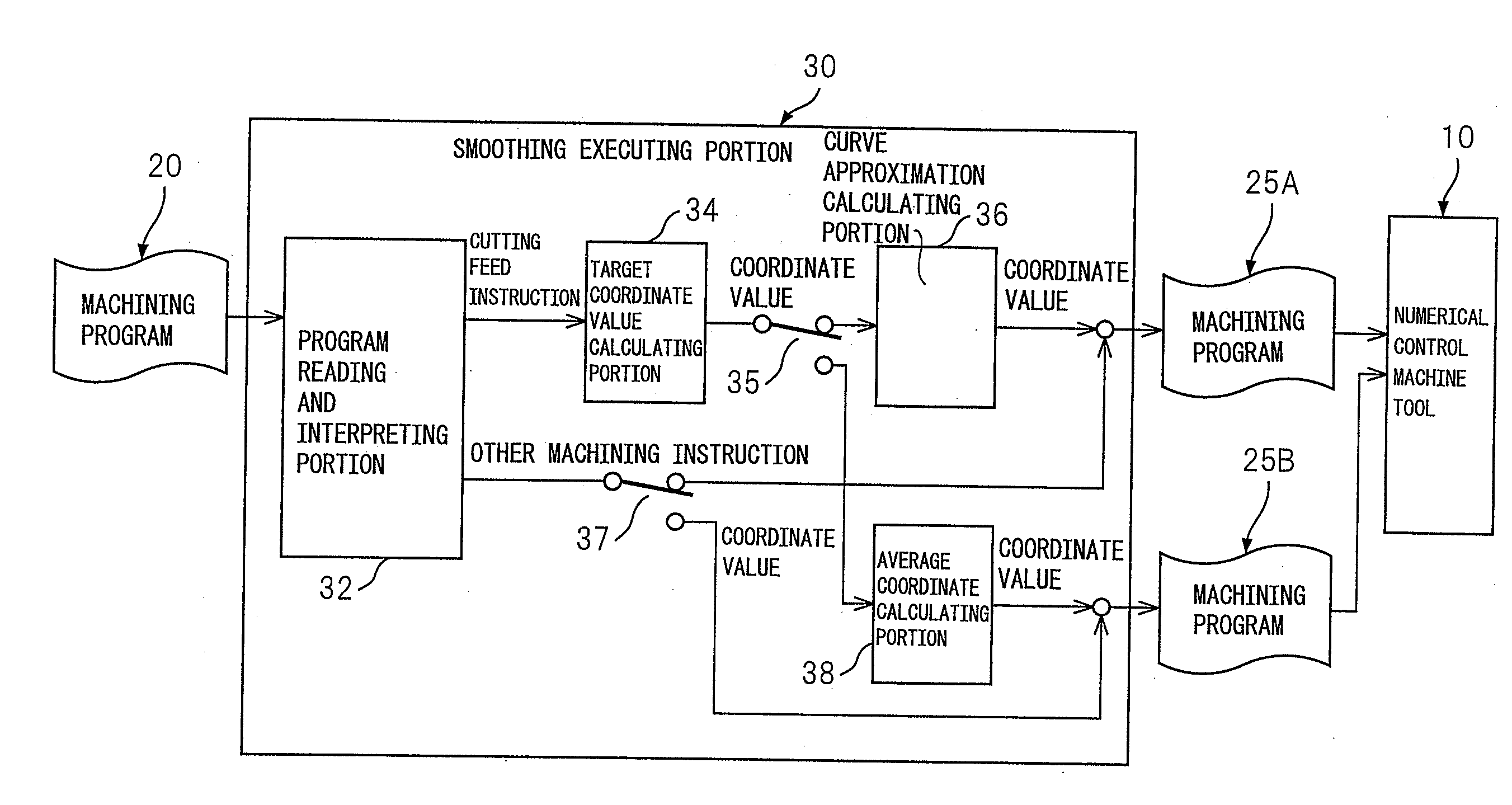
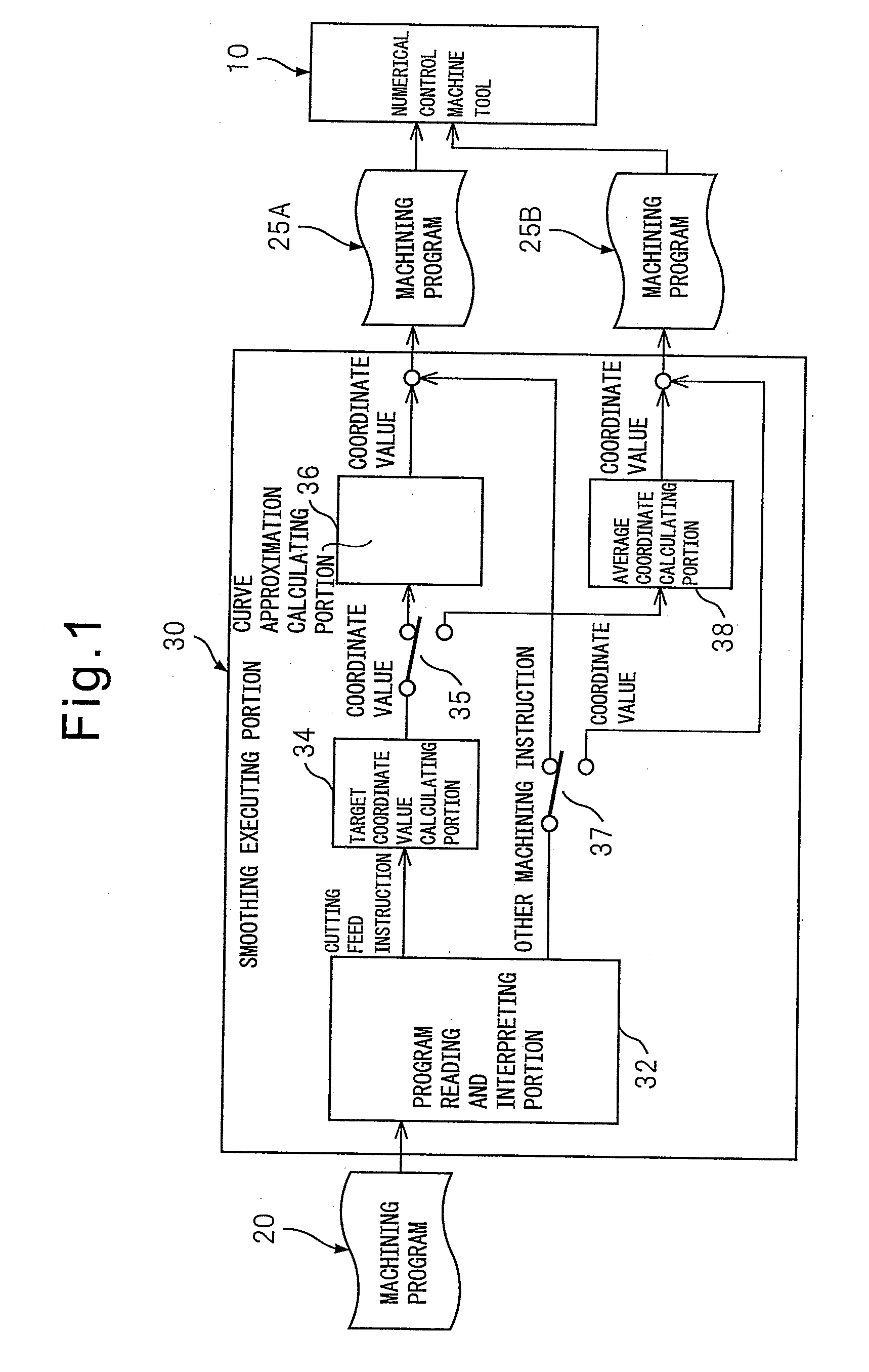
[0020]A tool path generation device of the present invention is not limited to the control device 15 which is used together with the numerical control machine tool 10 which is shown in this specification. It may also be used for a CAM system which prepares a machining program based on the CAD data of a workpiece, a numerical control machine tool which has a built-in control device, or a personal computer. The control device 15 can read in a machining program which is prepared by a CAM system, then perform smoothing to generate a tool path, and use the generated tool path to rewrite the machining program 20. The rewritten machining programs 25A and 25B are stored in the memory in the system and can be read out for use in another machine tool or partially edited in contents of the machining programs. Note that, it is also possible to configure the system in a manner not provided with the function of rewriting the machining program or the function of storing the machining program. The ...


PUM


Abstract

A tool path generation device for machining a workpiece with a machine tool including a reading and interpreting portion which reads out a tool path from a machining program, a target coordinate value calculating portion which sets a plurality of target points at equal intervals on the read out tool path, and a curve approximation calculating portion which generates a tool path based on the plurality of target points, so as to obtain a smooth machined surface without formation of step differences between adjacent tool paths.

Description

REFERENCE TO RELATED APPLICATIONS[0001]This application is the national stage under 35 USC 371 of International Application No. PCT / JP2010 / 069762, filed Oct. 29, 2010, which claims priority from Japanese Patent Application No. 2009-250638, filed Oct. 30, 2009, the entire contents of which are incorporated herein by reference.FIELD OF THE INVENTION[0002]The present invention relates to a tool path generation method and device for machining a workpiece with a machine tool.BACKGROUND OF THE INVENTION[0003]A machining program includes movement instructions for feed axes of a machine tool. The movement instructions include information on positions. A tool is made to move relative to a workpiece at a predetermined speed up to a predetermined position so that the workpiece is machined to a predetermined shape. The path of movement of the tool, that is, the tool path, is prepared by converting the CAD data which is the information of the workpiece drawings, to line information by a CAM syst...

Claims


Application Information

Patent Timeline
Patent Type & Authority Applications(United States)
IPC IPC(8): G06F17/50
CPCG05B19/4103G05B19/4099G05B2219/34143B23Q15/00
Inventor TANUMA, MASASHIODA, MITSUNARIKOMORI, TAKASHI
Owner MAKINO MILLING MASCH CO LTD
Learn More