
System for applying a diffusion aluminide coating on a selective area of a turbine engine component

a technology of diffusion aluminide and turbine engine, which is applied in the direction of solid-state diffusion coating, machines/engines, feeding apparatus, etc., can solve the problems of poor handling of components, ineffective removal of remaining undamaged coatings and re-coating the entire turbine component, and reduce the heat up cycle time and cool down cycle time. , the effect of cost saving

Inactive Publication Date: 2006-02-07
GENERAL ELECTRIC CO
View PDF21 Cites 31 Cited by
  • Summary
  • Abstract
  • Description
  • Claims
  • Application Information

AI Technical Summary

Benefits of technology

"The present invention provides an improved method for applying diffusion aluminide coating on a selective area of a turbine engine component using a quartz infrared lamp to heat only the localized area. This method allows for the formation of a distortion-free, aluminided engine component without requiring the heating up and cooling down of a large mass comprised of aluminum oxide powder plus the entire component. Additionally, the process reduces labor costs and is more environmentally friendly. The technical effects of this invention include cost savings, improved performance, and reduced waste."

Problems solved by technology

This chipping damage may he caused during machining of the aluminide coated component, by poor handling of the component during subsequent manufacturing processes, during routine maintenance or through the normal operational environment of the turbine component.
When repairing chipping damage, it is not cost effective to remove the remaining undamaged coating and re-coat the entire turbine component.
However, built up stress from the thermal expansion mismatch between the engine component and the inert aluminum oxide powder creates warpage or distortion of the selectively coated engine component, making the component unusable in the engine.
The unusable component must be discarded at great cost.

Method used


Image

  • System for applying a diffusion aluminide coating on a selective area of a turbine engine component
  • System for applying a diffusion aluminide coating on a selective area of a turbine engine component
  • System for applying a diffusion aluminide coating on a selective area of a turbine engine component

Examples


example 1

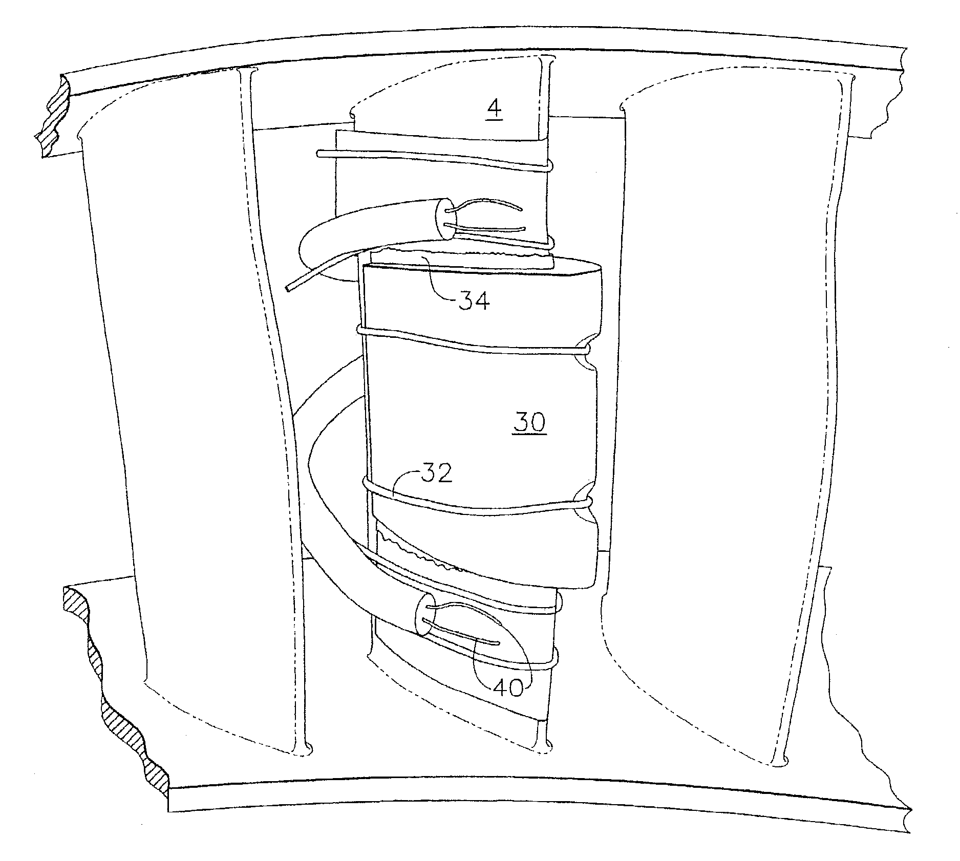
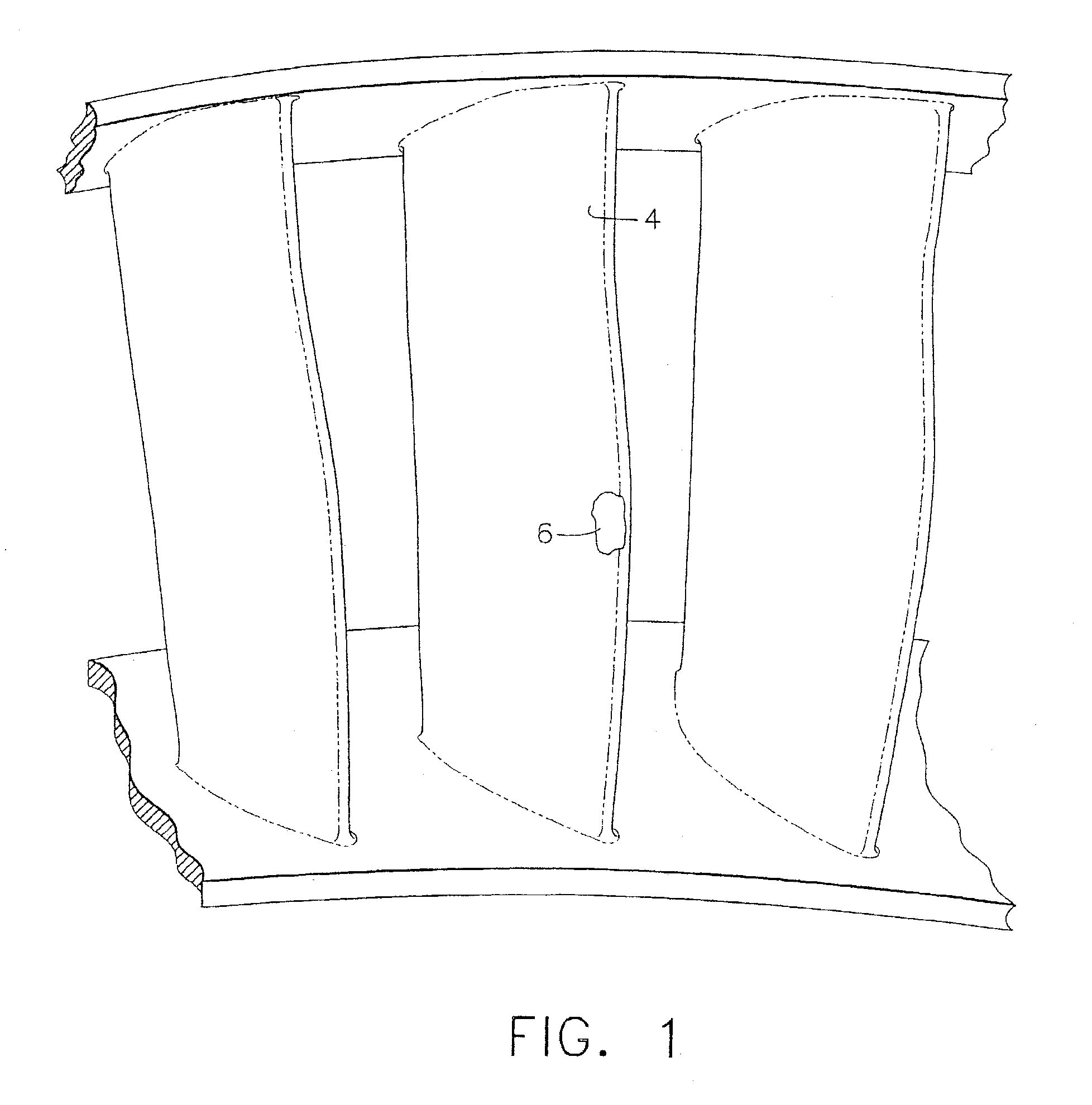
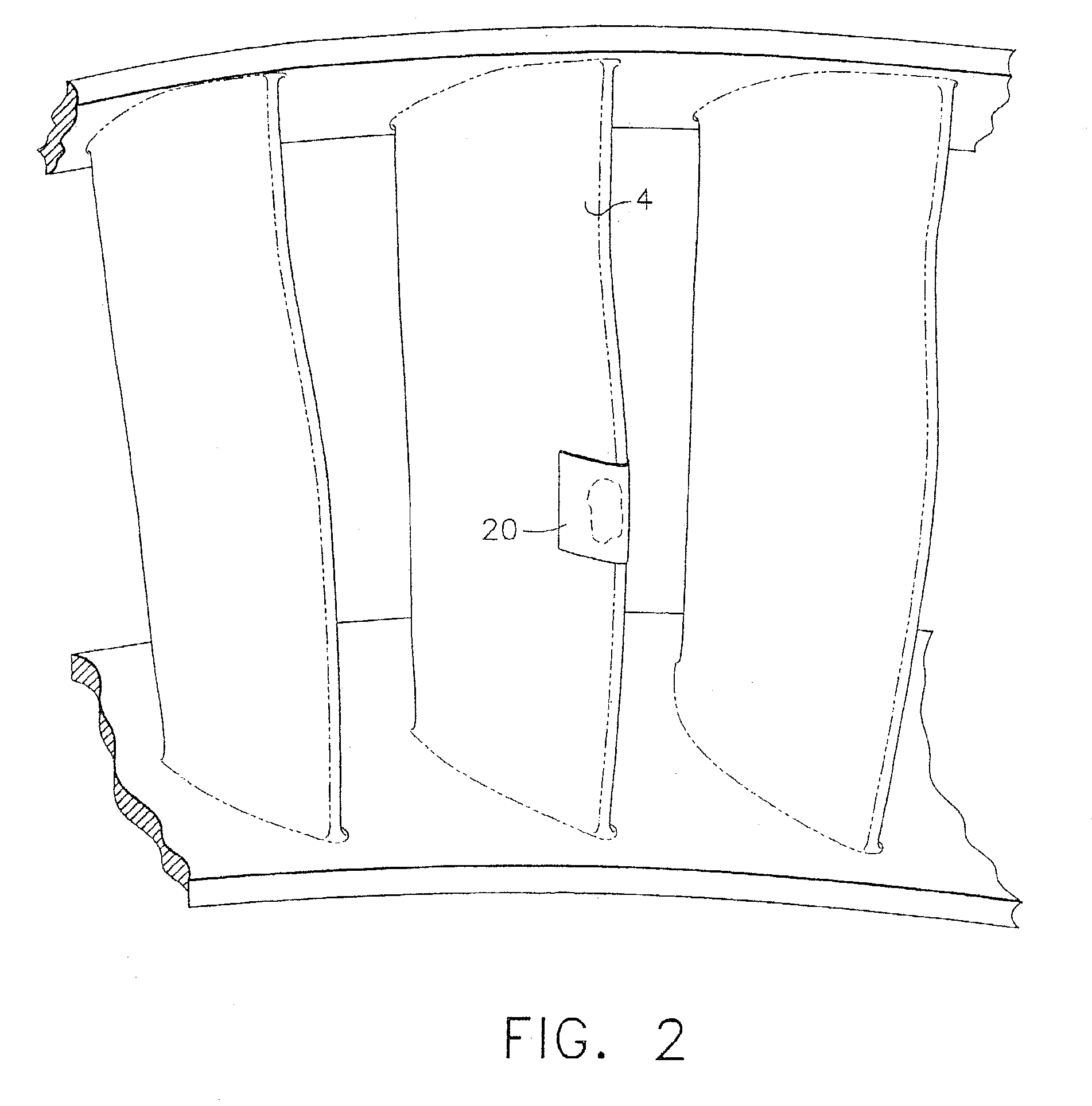
[0036]A coated scrap aircraft engine vane segment manufactured from René 77 nickel-based superalloy was coated and the coating was intentionally damaged. Aluminide coating was removed from a small area of the convex side trailing edge of the airfoil exposing substrate metal to simulate chipping. Halide activated self-adhesive CODAL tape was applied to the small area of exposed substrate and held in place using a graphite tape holder and graphite felt. Two thermocouples were placed adjacent to the exposed area of substrate to be repaired for monitoring and to precisely control the coating temperature in combination with a controller.

[0037]The taped component was placed inside an argon atmosphere chamber and the small area having the exposed substrate was heated to 1925° F.+ / −25° F. temperature using a 12,000 watt quartz lamp for four hours. The lamp was cycled by the controller to maintain temperature within the temperature range.

[0038]Inspection of the repaired vane segment showed n...


PUM

PropertyMeasurementUnit
temperaturesaaaaaaaaaa
thicknessaaaaaaaaaa
temperatureaaaaaaaaaa

Abstract

A method for applying diffusion aluminide coating on a selective area of a turbine engine component and the coating produced by that method is disclosed. A quartz infrared lamp heats only substantially the localized area of the component to be coated, rather than the complete part. Either halide activated or non-activated tape is applied on the area to be coated and is held in place during coating using a high temperature dimensionally stable tape holder manufactured from graphite or ceramic. The quartz infrared lamp is used to heat only the desired area to a coating temperature of about 1800° F. to about 2000° F. under an inert atmosphere for about 3 to about 8 hours to achieve the desired aluminide coating thickness. No powder masking of the machined surface area is required. Due to the localized heating, aluminum vapor generated from the tape will only deposit aluminide coating on the taped area.

Description

FIELD OF THE INVENTION[0001]The invention relates generally to components of the hot section of gas turbine engines, and in particular, to a diffusion aluminiding process for depositing an aluminide coating onto a selective area of a turbine component.BACKGROUND OF THE INVENTION[0002]In gas turbine engines, for example, aircraft engines, air is drawn into the front of the engine, compressed by a shaft-mounted rotary compressor, and mixed with fuel. The mixture is burned, and the hot exhaust gases are passed through a turbine mounted on a shaft. The flow of gas turns the turbine, which turns the shaft and drives the compressor. The hot exhaust gases flow from the back of the engine, providing thrust that propels the aircraft forward.[0003]During operation of gas turbine engines, the metal parts of the engine, are in contact with hot, corrosive gases. The metal parts require particular attention to protect them from these combustion gases. These metallic parts include blades and vanes...

Claims


Application Information

Patent Timeline
Patent Type & Authority Patents(United States)
IPC IPC(8): B21D53/78B23P6/00F01D5/28C23C10/04C23C10/28F02C7/00
CPCB23P6/005F01D5/288C23C10/04Y10T29/49316Y02T50/67Y02T50/672F05D2230/40F05D2300/121F05D2300/132F05D2300/2118Y10T29/49339Y10T29/37Y10T29/49318Y10T29/49742Y10T29/53096Y10T29/49732Y10T29/49336Y02T50/60
Inventor DAS, NRIPENDRA NATHHEIDORN, RAYMOND WILLIAMGMEREK, JR., WALTER MICHAELJABLONKA, DAVID ANDREW
Owner GENERAL ELECTRIC CO
Learn More