Roll-To-Roll Production of RFID Tags

a roll-to-roll production and tag technology, applied in the field of high-speed roll-to-roll production of rfid tag webstock, can solve the problems of tag manufacturing cost increase, tag production and handling in singulated, and limited performance at best, so as to avoid unnecessary proliferation of numbers

Active Publication Date: 2012-08-30
RFMICRON
View PDF11 Cites 35 Cited by
  • Summary
  • Abstract
  • Description
  • Claims
  • Application Information

AI Technical Summary

Benefits of technology

[0030]In the drawings, similar elements will be similarly numbered whenever possible. However, this practice is simply for convenience of reference and to avoid unnecessary proliferation of numbers, and is not intended to imply or suggest that our invention requires identity in either function or structure in the several embodiments.

Problems solved by technology

Furthermore, it is of no relevance in such systems which specific voltage levels are selected to represent each of the logic states.
Disadvantages of such prior art roll-to-roll manufactured tags include performance which is, at best, severely limited if the tag is attached proximate an interfering substance.
However, both thick substrates and additional metal layers add substantial cost to tag manufacturing.
In addition, the thickness required by prior-art designs has meant that tags had to be produced and handled in singulated form, rather than in long continuous rolls.
As a result, such prior-art metal-mount tags have not been adopted in high-volume applications that require high-speed automated processing using roll-form RFID labels.
Known efforts to decrease the thickness of the substrate of the final, converted tags using available RFID chips have proven impractical.
As the standoff distance gets below about 1 mm, it becomes economically impractical to attain the tight manufacturing tolerances required to manufacture metal-mount tags.
Thus, while some prior-art tags can be tuned to adjust for typical standoff distances, no known prior-art metal-mount tags can be manufactured reliably at standoff distances below about 1 mm.
Attempts also have been made to thin the substrate by using various specialized materials; however this typically adds unacceptable cost to the finished product.

Method used


Image

  • Roll-To-Roll Production of RFID Tags
  • Roll-To-Roll Production of RFID Tags
  • Roll-To-Roll Production of RFID Tags

Examples


Embodiment Construction

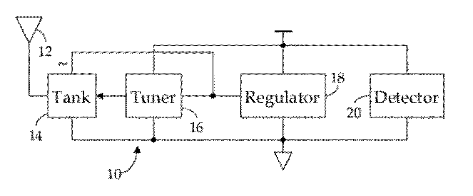
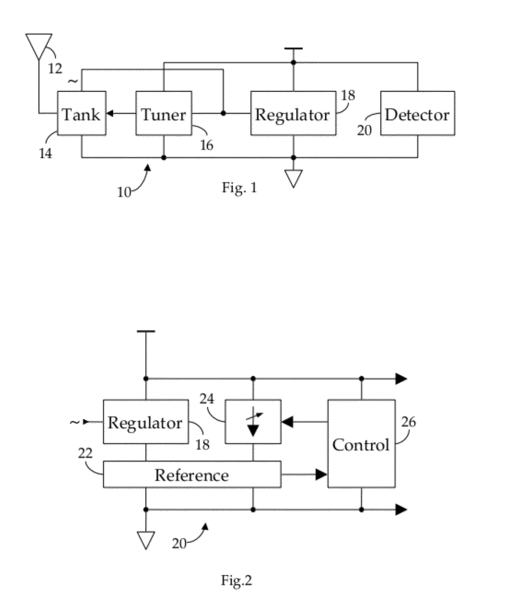
[0031]Shown in FIG. 1 is an RF receiver circuit 10 suitable for use in an RFID application. As we have described in our Related References, an RF signal electromagnetically coupled to an antenna 12 is received via a tank circuit 14, the response frequency, fR, of which is dynamically varied by a tuner 16 to better match the transmission frequency, fC, of the received RF signal, thus obtaining a maximum power transfer. In particular, as further noted in the Related References, the RMS voltage induced across the tank circuit 14 by the received RF signal is quantized by tuner 16 and the developed quantization employed to control the impedance of the tank circuit 14. As also described in the Related References, the unregulated, AC current induced in the tank circuit 14 by the received RF signal is conditioned by a regulator 18 to provide regulated DC operating power to the receiver circuit 10. In accordance with our invention, we provide a field strength detector 20, also known as a pow...


PUM

PropertyMeasurementUnit
standoff distanceaaaaaaaaaa
thicknessaaaaaaaaaa
standoff distancesaaaaaaaaaa

Abstract

A method and apparatus for manufacturing thin RFID tags adapted to be mounted proximate an interfering substance, such as metal or liquid. Each tag comprises: a web substrate having a predetermined thickness; an antenna attached to the substrate; and an RFID integrated circuit connected to the antenna, the RFID integrated circuit comprising a tank circuit adapted to be tuned in response to an RF signal after the tag has been mounted proximate the interfering substance. In one embodiment, the tag is manufactured using roll-to-roll manufacturing technology.

Description

CROSS-REFERENCE TO RELATED APPLICATIONS[0001]This application is a Continuation-In-Part of application Ser. No. 13 / 209,425, filed 14 Aug. 2011 (“Related Application”), which claims the benefit of the Parent Provisional Two and U.S. Provisional Application Ser. No. 61 / 428,170, filed 29 Dec. 2010 (“Parent Provisional One”). The Related Application is in turn a Continuation-In-Part of application Ser. No. 12 / 462,331, filed 1 Aug. 2009, now U.S. Pat. No. 8,081,043, issued 20 Dec. 2011 (“Related Patent One”), which is in turn a Division of application Ser. No. 11 / 601,085, filed 18 Nov. 2006, now U.S. Pat. No. 7,586,385, issued 8 Sep. 2009 (“Related Patent Two”).[0002]This application claims priority to U.S. Provisional Application Ser. No. 61 / 485,732, filed 13 May 2011, (“Parent Provisional Two”), and hereby claims benefit of the filing date thereof pursuant to 37 CFR §1.78(a)(4).[0003]This application is related to application Ser. No. 13 / 209,420, filed simultaneously with Application ...

Claims


Application Information

Patent Timeline
Patent Type & Authority Applications(United States)
IPC IPC(8): G06K19/067H01P11/00
CPCG06K19/0726G06K19/07718Y10T29/49016H03J2200/10H03J1/0075H03J3/20
Inventor ROKHSAZ, SHAHRIARDROBAC, STANLEY
Owner RFMICRON
Why Eureka
Try Eureka