Gas-filled neutron detectors having improved detection efficiency

a technology detectors, which is applied in the direction of radiation intensity measurement, instruments, x/gamma/cosmic radiation measurement, etc., can solve the problems of reducing the detection efficiency of gas-filled neutron detectors, and reducing the detection efficiency of neutron reactive gases. , to achieve the effect of increasing the detection efficiency of coated gas-filled neutron detectors

Active Publication Date: 2012-08-30
MCGREGOR DOUGLAS S
View PDF1 Cites 60 Cited by
  • Summary
  • Abstract
  • Description
  • Claims
  • Application Information

AI Technical Summary

Benefits of technology

[0063]The above-mentioned and other problems are solved by applying the principles and teachings associated with the hereinafter described different embodiments of compartmentalized gas-filled neutron detectors. Gas-filled detectors are designed such that one or more objects or structures having large surface areas are incorporated into the gas-filled detectors, where these surfaces are coated with neutron reactive material, or the surfaces or surface portions are composed, at least partially, of neutron reactive material. The surfaces or surface portions may be flat or curved fins or plates, porous or filamentary material, or semi-solid material or aerogel. The incorporation of the extended surfaces coated with or composed of neutron reactive material increases the neutron detection efficiency of the gas-filled detectors over conventional coated designs.
[0064]These surfaces or surface portions increase the amount of neutron reactive material present in the detectors over conventional coated designs and as a result increase the neutron detection efficiency. The one or more objects or structures can be made of conducting, semiconducting or insulating materials. The surfaces or surface portions are arranged such that they do not detrimentally detract from the main function of a gas-filled detector with particular attention to gas-filled proportional detectors. The use of porous media, such as foam, sponge, filamentary material, or aerogel, allows for neutron reactive structures to be inserted into the detector that allow for all reaction products resulting from at least one absorbed neutron to be released into the detector chamber and into the detector gas, a feature not possible with prior art coated neutron detectors.
[0065]An object of at least one embodiment of the present invention is to provide neutron detectors that have detection efficiencies many times greater than present coated gas-filled neutron detectors while remaining relatively inexpensive to construct.

Problems solved by technology

Quite differently, ion chambers do not produce 
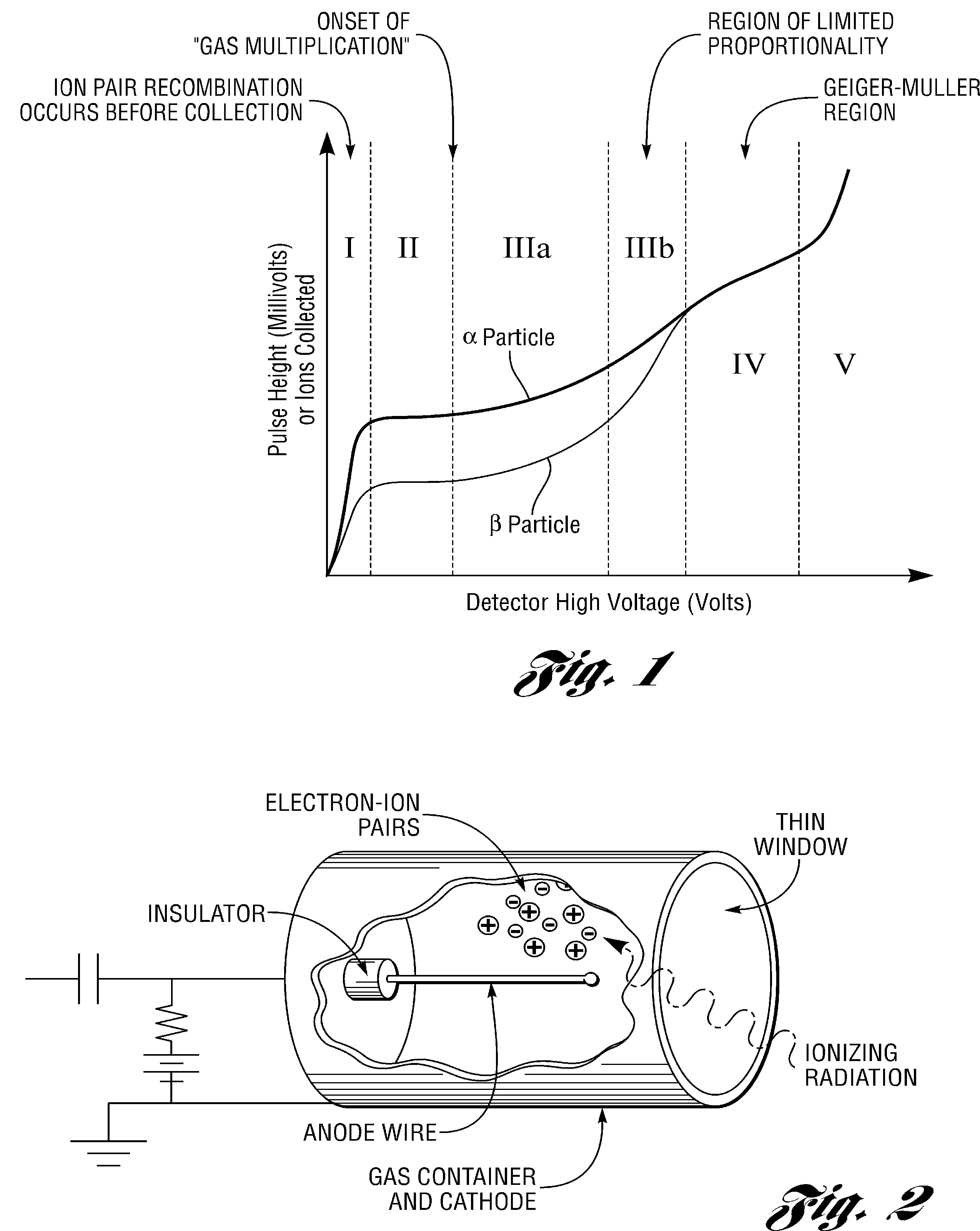
avalanche multiplication and Geiger-Mueller counters produce excessive avalanching such that the electronic signal is no longer proportional to the energy deposited in the chamber.
However, in recent times, these neutron reactive gases have been deemed hazardous, as is the case for BF3, or have become rare and difficult to acquire, as is the case for 3He.
The gas-filled neutron detector design with neutron reactive materials coating the walls does not suffer from these issues, yet these coated detectors have an intrinsic problem in that they are limited to relatively low neutron detection efficiency.
The low detection efficiency is a direct result of the reaction products having a limited range in the coating, hence any coating thicker than the reaction product particle ranges simply absorbs all of the particle energy, which is therefore not transferred to the detecting gas.
As a result, Gd-based films are less attractive for devices where background gamma ray contamination is a problem.
Thus far, thermal neutron detection efficiencies have been limited to only 4% for 6LiF and 10B single-coated devices.
Unfortunately, pure Li decomposes rapidly in most circumstances, making a pure Li coated device impractical at present.
As a result the most commonly used neutron converter films are B and LiF, both of which are poor electrical conductors.
Reaction product self-absorption reduces the energy transferred to the detector gas, and ultimately limits the maximum film thickness that can be deposited over the detector.
Hence, neutrons entering and exiting the gas detector are limited to a total efficiency of approximately 8.3%.
Although extremely useful, there are drawbacks to this method.
A pulse mode detector operated in low radiation fields has little problem with dead time count losses; however, a detector operated in high radiation fields may have significant dead time losses, thereby yielding an incorrect measurement of the radiation activity in the vicinity.
The disadvantage of current mode is that it does not identify individual radiation interactions.
Finally, excessive voltage drives the detector into Region V where the voltage causes sporadic arcing and other spontaneous electron emissions to occur, hence causing continuous discharging in the detector.
Although simple in concept, two main problems occur in the ion chamber for pulse mode operation, those being (1) the signal measured is small, due to the fact that the current measured is only from the primary (or initial) electron-ion pairs excited by the radiation quantum and (2) the signal formation time can be long due to the slow motion of the heavy positive ions.
Yet, as explained with the ion chamber, such a current can be minuscule and hard to measure.
Such electrons from photoionization can cause problems.
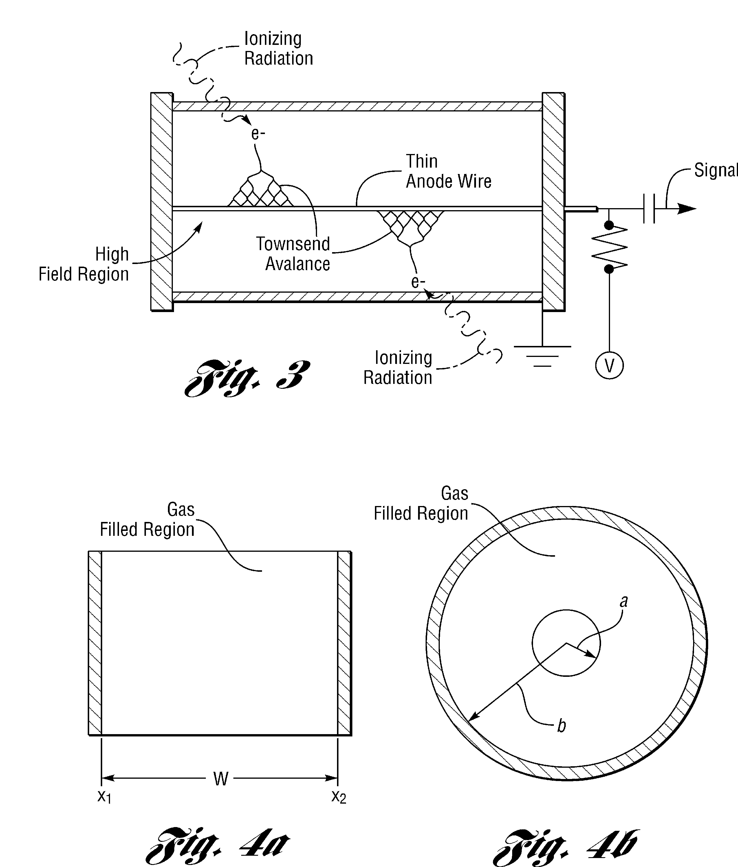
If, however, δf>1, the avalanching process becomes uncontrollable and the detector develops a self-sustaining discharge.
Electron and ion velocities decrease inversely proportional to gas pressure: consequently, increasing the gas pressure in the tube causes the counter dead time to increase.
Unfortunately 3He is relatively rare gas that has become expensive in recent times, thereby driving up the cost of these gas-filled detectors.
Further, 10BF3 is a poisonous gas and does have certain health risks associated with their production, use and disposal.
Unfortunately, the spectral features from such a device are harder to interpret due to interference from background gamma rays, and the total neutron detection efficiency is limited by the thinness of the optimum 10B absorber coating, typically only 2 to 3 microns thick.
Further, due to self absorption of energy as the reaction product travels through the neutron absorbing film to the detector gas, more energy can be lost, a significant problem with this type of detector.
Although the design increases the overall efficiency of the detector, it has a limit to the efficiency that can be realized.
A practical device will be limited to less than 35% detection efficiency of thermal neutrons if the device is irradiated end on, reducing to almost 0% if irradiated from the side.
The gas in this style of detector is not replenished and can be exhausted over a period of time.
The detector efficiency of FIG. 10 is usually low, limited to less than 10%.
Hence, Geiger-Mueller counters do not intrinsically possess the ability to discern between alpha, beta, or gamma radiation, nor can they distinguish between different energies of these radiations.
This large accumulation of positive ions near the anode affects the electric field and reduces its strength.
Lastly, because Geiger-Mueller counters are typically closed tubes, the quenching gas inside can be exhausted over time if traditional organic molecules such as the methane component of P-10 gas are used.
Considering equations 1 and 2, gas-filled detectors relying upon neutron reactive coatings are limited to low efficiencies due to reaction product self-absorption.
As a result, the maximum efficiency that the device can have will be limited to less than 10% thermal neutron detection efficiency.
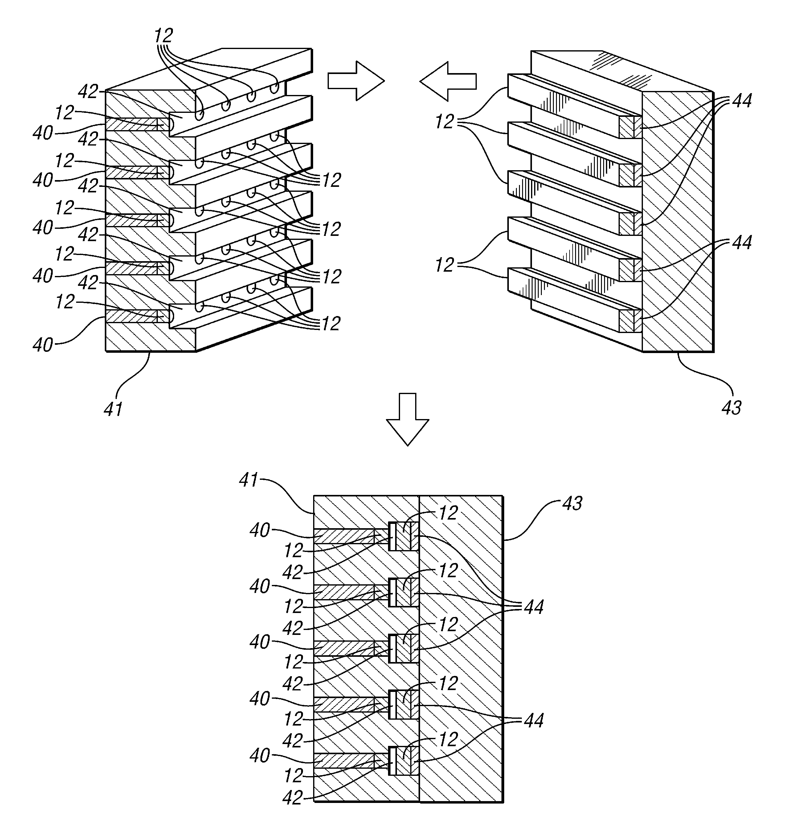
Detectors with washers coated with neutron reactive material aligned down the axis of a detector can increase the neutron detection efficiency, but are ineffective when irradiated from the side and are designed to point end on at the neutron source.

Method used


Image

  • Gas-filled neutron detectors having improved detection efficiency
  • Gas-filled neutron detectors having improved detection efficiency
  • Gas-filled neutron detectors having improved detection efficiency

Examples


example embodiments

SUMMARY OF EXAMPLE EMBODIMENTS

[0274]The above-mentioned and other problems are solved by applying the principles and teachings associated with the hereinafter described different embodiments of compartmentalized gas-filled neutron detectors. Gas-filled detectors are designed such that one or more objects or structures having large surface areas of low-density, ultra-low-density, or are ultra-thin are incorporated into the gas-filled detectors, where these structures are either composed entirely, or partially, from neutron reactive materials. The low-density and ultra-low-density structures allow the reaction products to travel further than in typical solids, thus the reaction products may escape multiples sides of a neutron absorbing structure concurrently and be measured in the non-reactive gas volume simultaneously. As a result of using materials, which are usually solids, as low-density or ultra-low-density materials, they may become porous or filamentary and have large surface a...


PUM


Abstract

Surfaces or surface portions incorporated into gas-filled neutron detectors are coated with and / or composed of at least partially, neutron reactive material. The surfaces may be flat or curved fins or plates, foils, porous or filamentary material, or semi-solid material or aerogel. The incorporation of the extended surfaces coated with or composed of neutron reactive material increases the neutron detection efficiency of the gas-filled detectors over conventional coated designs. These surfaces or surface portions increase the amount of neutron reactive material present in the detector over conventional coated designs and, as a result, increase the neutron detection efficiency. The surfaces can be made of conductive, semiconductive or insulative materials. The surfaces are arranged such that they do not detrimentally detract from the main function of a gas-filled detector with particular attention to gas-filled proportional detectors.

Description

CROSS-REFERENCE TO RELATED APPLICATION[0001]This application is a continuation-in-part of U.S. national phase of PCT Appln. No. PCT / US 2010 / 046736, filed Aug. 26, 2010, which claims the benefit of U.S. provisional patent application No. 61 / 275,278, filed Aug. 27, 2009, the disclosures of which are hereby incorporated by reference in their entirety.TECHNICAL FIELD[0002]This invention generally relates to gas-filled radiation detectors and, in particular, to gas-filled radiation detectors designed to detect neutrons of various energy ranges in the form of a large vessel with inserts at least partially composed of neutron reactive or absorbing material.BACKGROUND AND BACKGROUND ART[0003]Gas-filled detectors are arranged in three various forms, those forms being ion chambers, proportional counters, and Geiger-Mueller counters. Of these basic forms, the proportional counter design is often used as the fundamental instrument for a gas-filled neutron detector. Proportional counters rely up...

Claims


Application Information

Patent Timeline
Patent Type & Authority Applications(United States)
IPC IPC(8): G01T3/06
CPCG01T3/008G01T3/00
Inventor MCGREGOR, DOUGLAS S.BELLINGER, STEVEN L.MCNEIL, WALTER J.OHMES, MARTIN F.NELSON, KYLE A.
Owner MCGREGOR DOUGLAS S
Why Eureka
Try Eureka