System and Method for Automatically Optimizing Wireless Power

Active Publication Date: 2012-08-30
MITSUBISHI ELECTRIC RES LAB INC
View PDF10 Cites 78 Cited by
  • Summary
  • Abstract
  • Description
  • Claims
  • Application Information

AI Technical Summary

Benefits of technology

[0010]The embodiments of the invention are based on a realization that an array of strongly coupled resonant objects extends the range of efficient wireless energy transfer and facilitates an efficient energy transfer to receiving objects moving over a large distance.
[0011]Embodiments of the invention are based on another realization that, if the energy is provided to at least one object of an array of strongly coupled resonant objects, the energy oscillates among all objects in the array with reasonable losses. If the energy is provided to at least one object in the array, the energy is distributed from the object to all other objects in the array. Thus, the sink can receive energy wirelessly from any object of the array. Accordingly, the embodiments of the invention provide a novel way to store and distribute energy for subsequent wireless retrieval of the energy at any desired direction and distance from the energy driver.
[0012]In conventional energy distribution systems, the energy is transmitted over a closed loop to return the unused energy back to the source or to other specially designed energy storages. That was not considered as a problem, but rather as a fact of the energy transfer. The embodiments of the invention eliminate this requirement allowing arbitrarily arrangements of the objects and thus, arbitrarily configuration of energy distribution topography.

Problems solved by technology

To optimize the energy, a distance between the source and the sink should be as small as possible, because over greater distances the inductive coupling method is highly ineffective.
However, the resonant coupling transfers energy from the source to the sink over a mid-range distance, e.g., a few times of the resonant frequency wavelength, is inefficient when the distance becomes larger.

Method used


Image

  • System and Method for Automatically Optimizing Wireless Power
  • System and Method for Automatically Optimizing Wireless Power
  • System and Method for Automatically Optimizing Wireless Power

Examples


example

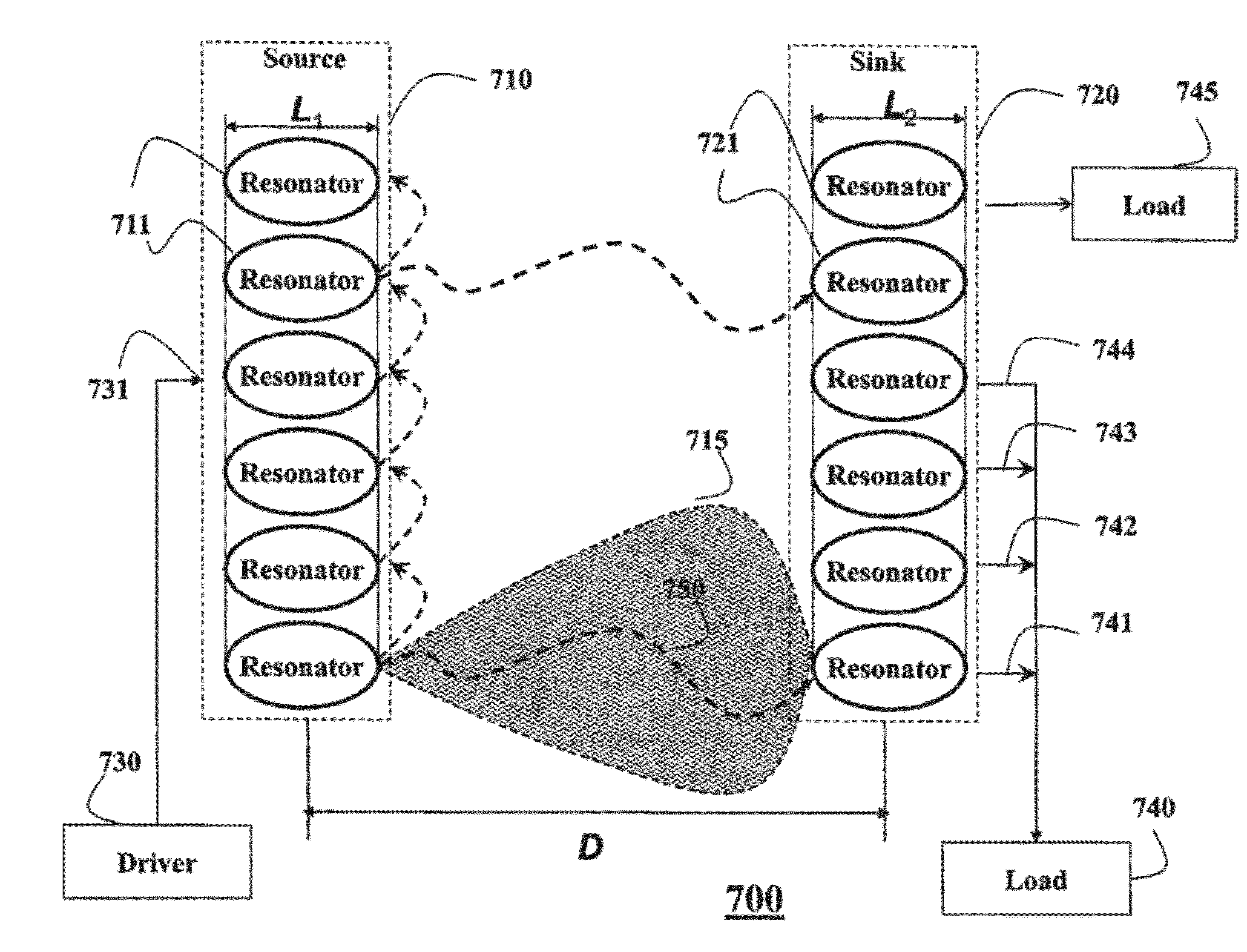
[0081]FIG. 9 shows another example embodiment. Spiral resonators 910 resonating at 27 MHz form the resonator arrays of the source 920 and the sink 930. For example, both resonator arrays have six spiral elements separated by a distance D1. Two loop antennas with R radius are used as the energy driver 940 and the load 950. The separation between driver / load and source array / sink array is D2. The distance between the source and sink array is D.

[0082]For example, the energy is provided to the energy driver 940 via wired cable and then provided to the source via, e.g., inductive coupling at resonant frequency. The specified resonant mode is excited in the system and the energy redistributed over the whole system according to the resonant mode. The load 950 extracts the energy wirelessly from the sink 930. When the energy is extracted from the system, energy balance of the system is disturbed and more energy is provided from the driver 940 to maintain the balance. Accordingly, the energy...


PUM


Abstract

A system transfers energy wirelessly from a source to a sink as an EM near-field according to parameters. The source includes a receive RF chain, and a receive controller. The sink includes a transmit RF chain, and a receive controller. The receive controller measures the energy received as feedback information, which is transmitted to the sink. Then, the transmit controller dynamically varies the parameters to optimized the energy received at the sink.

Description

RELATED APPLICATION[0001]The present invention claims priority to U.S. Provisional Patent Application 61 / 447,599, “Wireless Energy transfer Using Array of Resonant Objects,” filed by Wang et al. on Feb. 28, 2011, and is related to U.S. patent application Ser. No. 13 / 209,297 “Wireless Energy transfer Using Arrays of Resonant Objects,” co-filed herewith by Wang et al. on Aug. 12, 2011, and U.S. patent application Ser. No. 13 / 209,336 “Tuning electromagnetic fields characteristics for wireless energy transfer using arrays of resonant objects,” co-filed herewith by Wang et al. on Aug. 12, 2011, all incorporated herein by reference.FIELD OF THE INVENTION[0002]The present invention relates generally to transferring energy wirelessly, and more particularly to transferring energy using arrays of resonant objects.BACKGROUND OF THE INVENTION[0003]Wireless Energy Transfer[0004]Inductive coupling is used in a number of wireless energy transfer systems, such as a cordless electronic toothbrush, o...

Claims


Application Information

Patent Timeline
IPC IPC(8): H02J17/00
CPCH02J5/005H02J17/00H04B5/0087H04B5/0081H04B5/0037Y02T10/7072Y04S30/14B66B7/00B60L53/65H02J50/12Y02T90/12Y02T90/167Y02T10/70H02J50/05H02J50/40H02J50/10H04B5/263H04B5/26H04B5/79H02J50/70Y02T90/14Y02T90/16H02J50/20
Inventor YERAZUNIS, WILLIAM S.WANG, BINGNANDUAN, CHUNJIEBARNWELL, JOHNBURNS, DAN J.
Owner MITSUBISHI ELECTRIC RES LAB INC
Why Eureka
Try Eureka