
Compact and adjustable LED lighting apparatus, and method and system for operating such long-term

a technology of led lighting apparatus and long-term operation, which is applied in the direction of lighting and heating apparatus, lighting support devices, instruments, etc., can solve the problems of limited ability to predict or assure a certain number of operating hours, insufficient characterization, and insufficient understanding of long-term behavior of led lighting apparatus, so as to ensure the longevity of leds

Active Publication Date: 2012-08-30
MUSCO
View PDF17 Cites 62 Cited by
  • Summary
  • Abstract
  • Description
  • Claims
  • Application Information

AI Technical Summary

Benefits of technology

[0009]According to the present invention, a lighting system is provided whereby a number of operating hours can be reasonably ensured for a particular combination of LED and fixture. Through the envisioned power compensation methodology and effective luminaire design, a relatively constant light level can be assured for the defined lifespan of the system; this is true even if operating conditions change, the known behavior of LEDs proves untrue over untested periods of time, or some other condition occurs which would otherwise cause EOL prematurely and prevent the system from meeting the desired number of operating hours.
[0015]e. a robust luminaire design suitable for outdoor use; and
[0016]f. means to correct for undesirable operating conditions so to aid in ensuring the longevity of LEDs in said LED fixtures.

Problems solved by technology

This is problematic because the longevity of LEDs is highly dependent on operating conditions—many of which cannot be closely controlled—thus limiting the ability to predict or assure a certain number of operating hours.
Further, LEDs are not fully characterized so their behavior long-term is not well understood.

Method used


Image

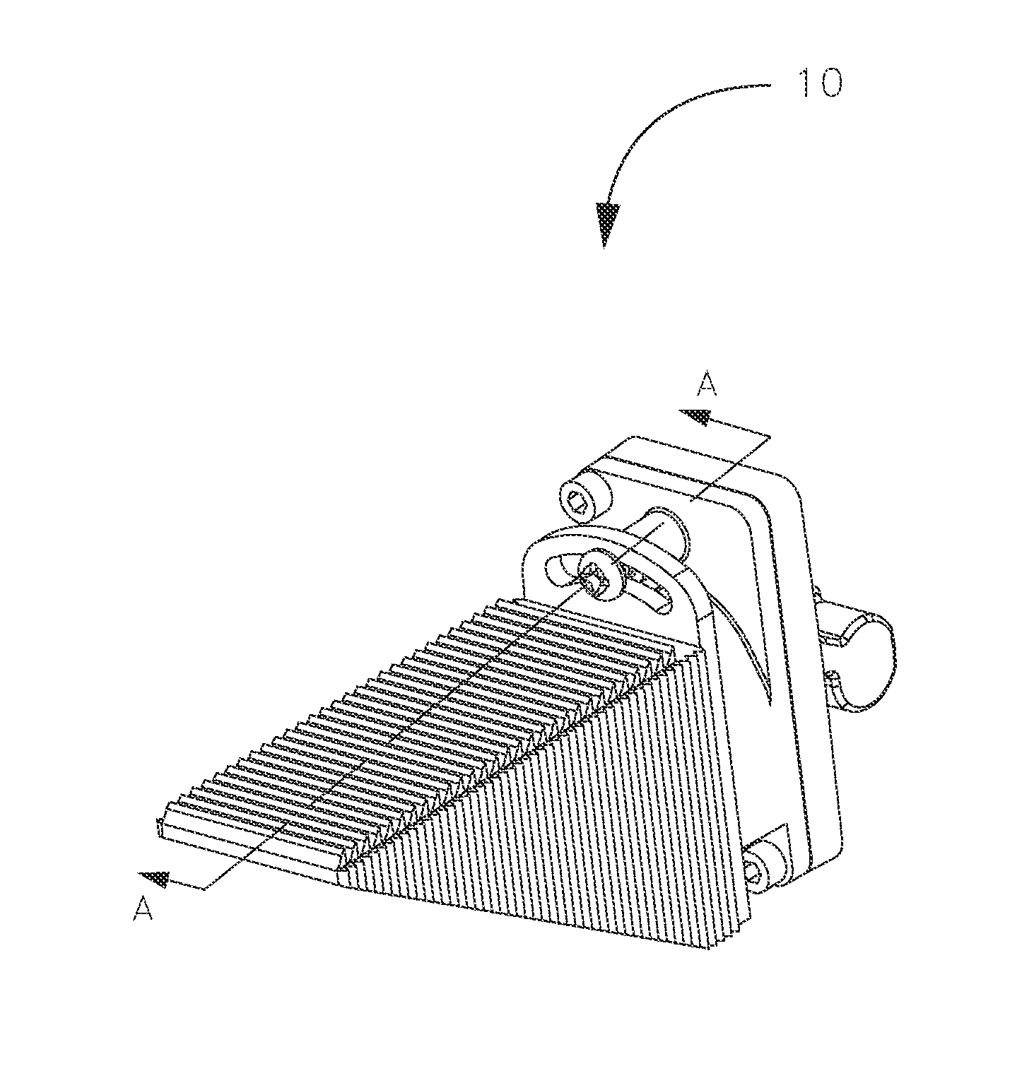
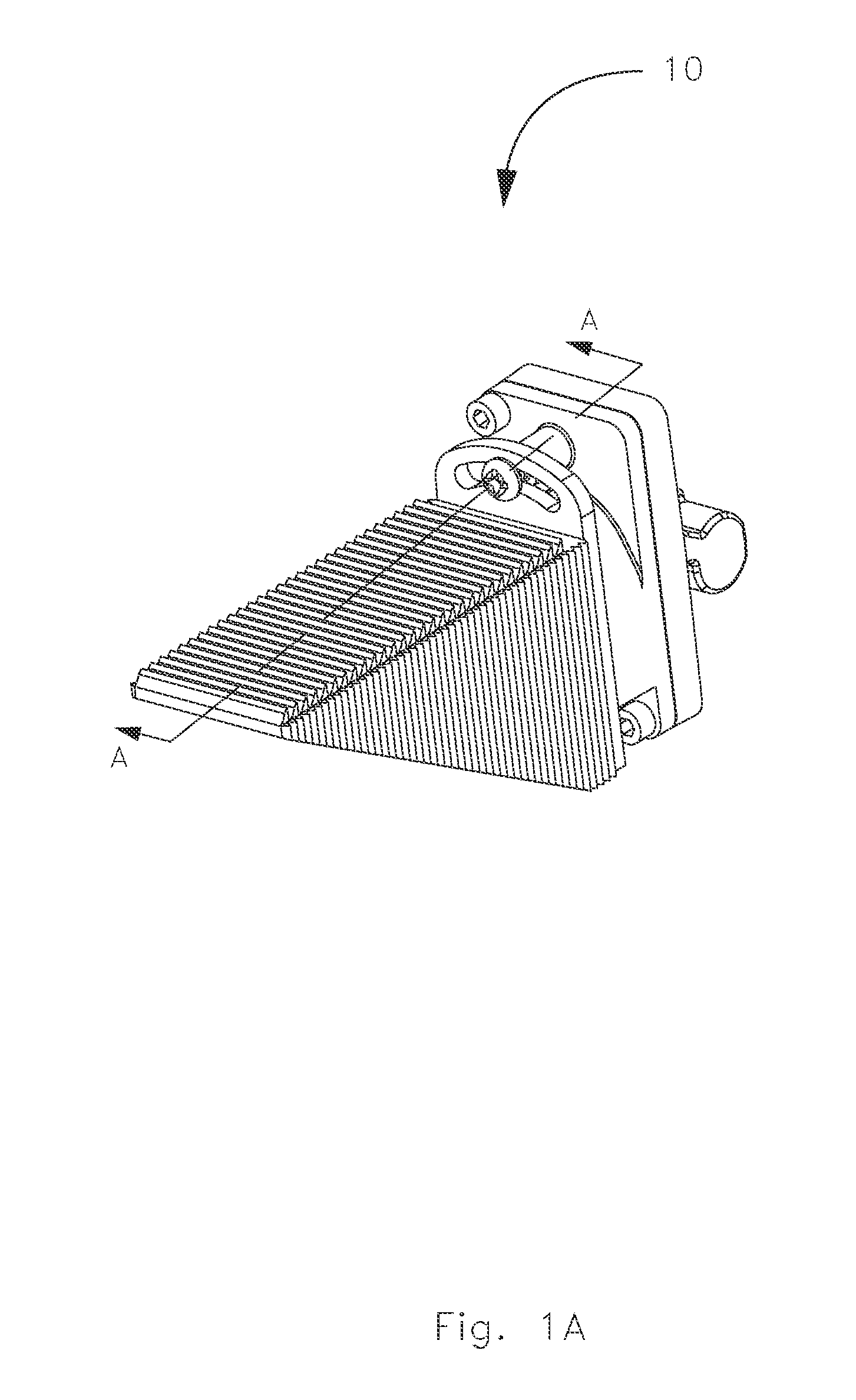
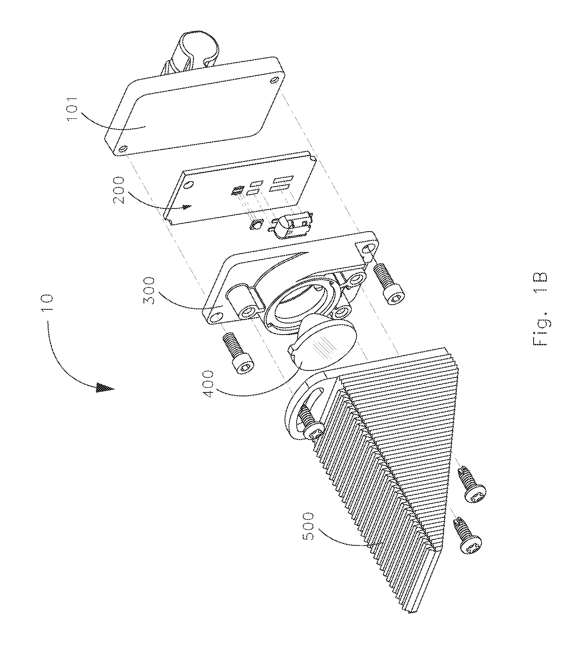
  • Compact and adjustable LED lighting apparatus, and method and system for operating such long-term
  • Compact and adjustable LED lighting apparatus, and method and system for operating such long-term
  • Compact and adjustable LED lighting apparatus, and method and system for operating such long-term

Examples


Embodiment Construction

[0055]To further an understanding of the present invention, specific exemplary embodiments according to the present invention will be described in detail. Frequent mention will be made in this description to the drawings. Reference numbers will be used to indicate certain parts in the drawings. The same reference numbers will be used to indicate the same parts throughout the drawings.

[0056]Envisioned are apparatus, methods, and systems for reasonably ensuring operation of a large-scale outdoor LED lighting system over a defined period of time at a relatively constant light level. LEDs offer many benefits including long operating life, RoHS and LEED compliance, no restrike downtime, good color stability even across dimming levels, and high efficacy to name a few. That being said, it is to be understood that aspects of the present invention could be applied to other lighting applications, other types of light sources, and the like. Further, while a variety of options and alternatives ...


PUM

PropertyMeasurementUnit
vertical aiming angleaaaaaaaaaa
structureaaaaaaaaaa

Abstract

A lighting system is provided whereby long operating life can be reasonably ensured by taking into account requirements of the application, characteristics of the LEDs, characteristics of the fixture containing said LEDs, the desired number of operating hours, and—via developed relationships—taking an iterative approach to supplying power to the LEDs. Through the envisioned compensation methodology and effective luminaire design, a relatively constant light level can be assured for a predetermined number of operating hours (possibly longer); this is true even if operating conditions change, known behavior of LEDs proves untrue over untested period of time, or some other condition occurs which would otherwise cause end-of-life prematurely and prevent the system from meeting the desired number of operating hours.

Description

CROSS-REFERENCE TO RELATED APPLICATIONS[0001]This application claims priority under 35 U.S.C. §119 to provisional U.S. Application Ser. No. 61 / 446,915, filed Feb. 25, 2011 which is hereby incorporated by reference in its entirety.I. BACKGROUND OF THE INVENTION[0002]The present invention generally relates to light-emitting diodes (LEDs), and more particularly, to the design of a lighting apparatus and lighting system using such in a manner that maximizes the benefits of LEDs to satisfy difficult lighting requirements.[0003]By now it is well known that the use of LEDs in general lighting applications yields substantial benefits: long operating life, high efficacy, and precise control of light are at the forefront. However, it is also well known that to get the most out of LEDs a number of factors must be considered: temperature (both ambient and junction) and luminaire design, for example. LEDs are quickly becoming the light source of choice for architectural or aesthetic lighting app...

Claims


Application Information

Patent Timeline
Patent Type & Authority Applications(United States)
IPC IPC(8): H05B37/02F21V7/00F21V19/02F21S8/00
CPCF21V29/004Y10T29/49826F21S8/086F21V5/04F21V7/00F21V11/00F21V17/002F21V17/005F21V21/30F21V23/008F21V23/0435F21V23/0442F21W2131/103F21W2131/105F21Y2101/02F21V29/763F21V31/005F21Y2115/10
Inventor GORDIN, MYRONBOYLE, TIMOTHY J.STONE, THOMAS A.
Owner MUSCO
Learn More