Method and apparatus for coating or heat treatment of blisks for aircraft gas turbines

a technology for aircraft gas turbines and blisks, which is applied in the direction of vacuum evaporation coating, liquid fuel engine components, chemical vapor deposition coatings, etc., can solve the problems of reducing the service life of the other parts of the blisk, coating or heat treatment processes, respectively, and achieve the effect of not affecting the service life of the blisk

Inactive Publication Date: 2008-08-19
ROLLS ROYCE DEUT LTD & CO KG
View PDF18 Cites 2 Cited by
  • Summary
  • Abstract
  • Description
  • Claims
  • Application Information

AI Technical Summary

Benefits of technology

[0004]This invention, in a broad aspect, provides a coating or heat treatment method, and an apparatus for the performance of this method, which enable the blade airfoils to be repaired and heat-treated or coated many times, without affecting the service life of the blisk as a whole.
[0006]According to the method proposed, exposure to the high temperatures occurring during elevated-temperature hard-material coating or heat treatment of blade airfoils is confined to the blade airfoils, while the other parts of the blisk are insulated against the hot environment and are partially cooled by heat transfer to a solid medium and a fluidic cooling medium, as a result of which they will not exceed the maximum operating temperature. In other words, the idea underlying the present invention is to heat-treat / coat one part of the blisk while cooling and insulating the other. Thus, the operationally highly loaded disk remains fully serviceable and attains a long service life even after multiple heat treatments or coatings. Furthermore, the serviceability of the less loaded blade airfoils is not affected by the influence of heat. The possibility of hard-material coating or heat treatment of repaired blade airfoils so created ensures the longevity of the blisks.

Problems solved by technology

The coating or the heat-treatment processes, respectively, are, however, disadvantageous in that, simultaneously with the blade airfoils, the blade platforms and the actual disk are heated to a temperature that exceeds the maximum operating temperature.
While this high process temperature does not constitute a serious problem for the less loaded stressed blade airfoils, it can cause geometrical distortion, affect serviceability and, ultimately, lead to a reduction of service life of the other parts of the blisk.

Method used


Image

  • Method and apparatus for coating or heat treatment of blisks for aircraft gas turbines
  • Method and apparatus for coating or heat treatment of blisks for aircraft gas turbines
  • Method and apparatus for coating or heat treatment of blisks for aircraft gas turbines

Examples


Embodiment Construction

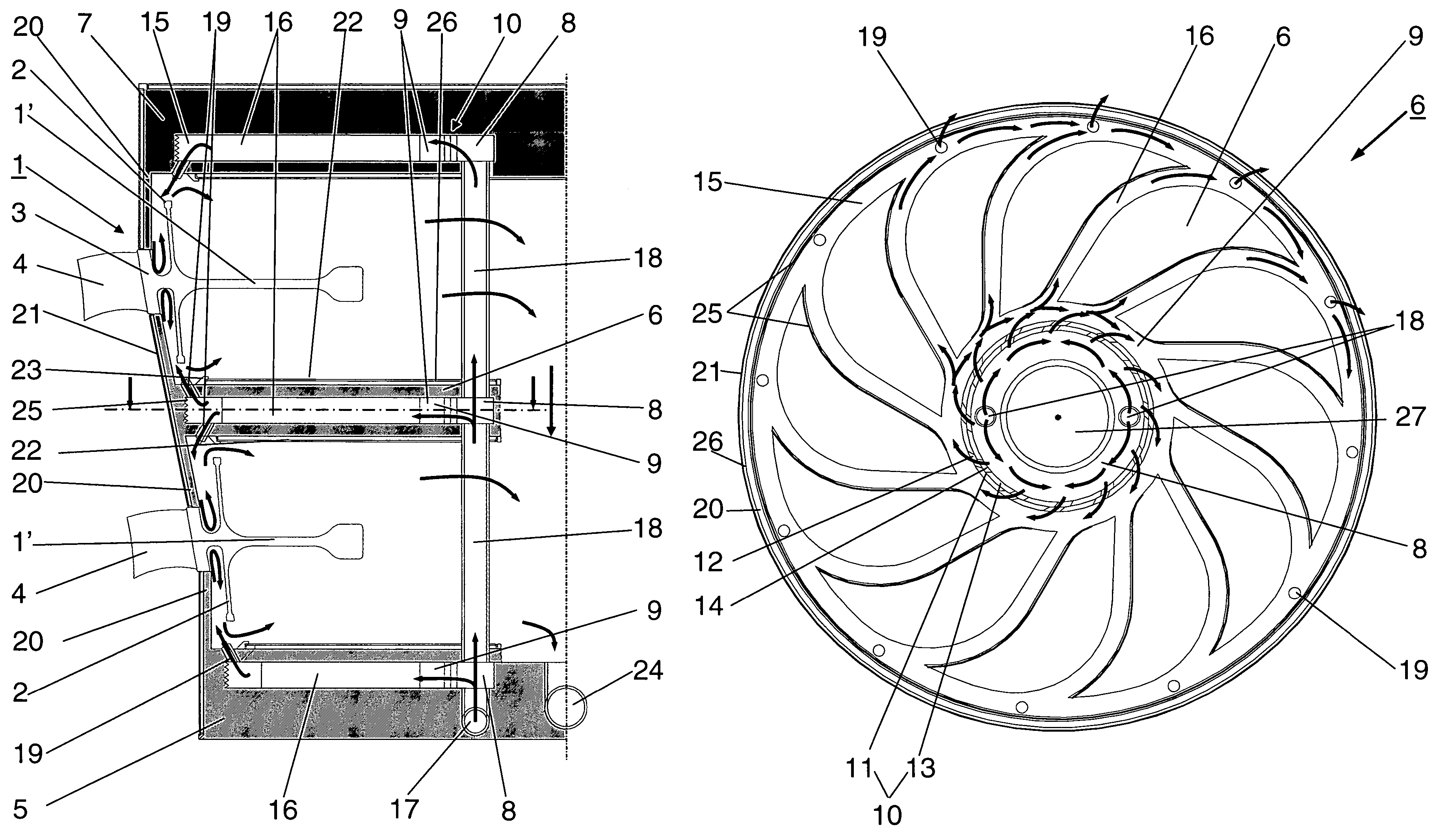
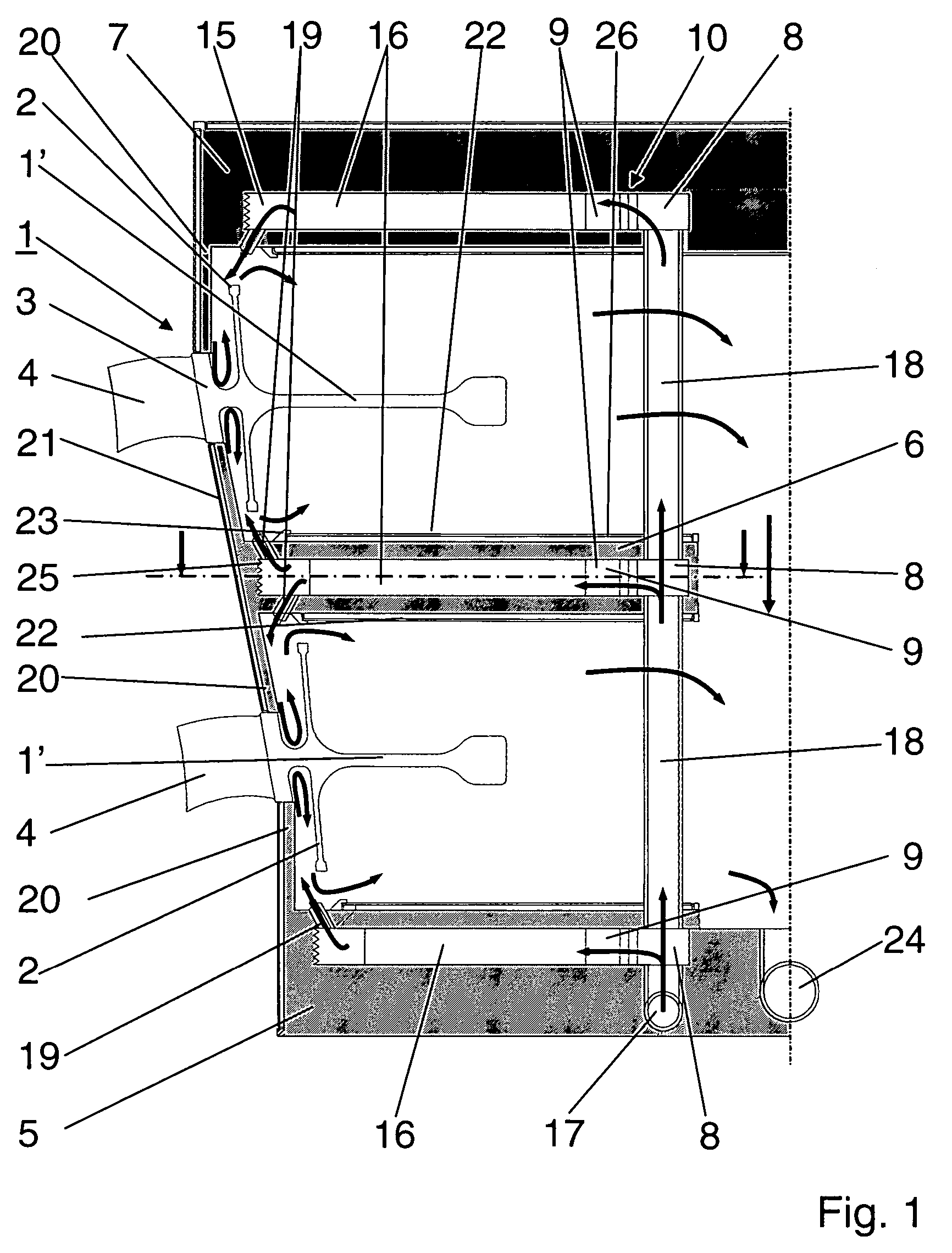
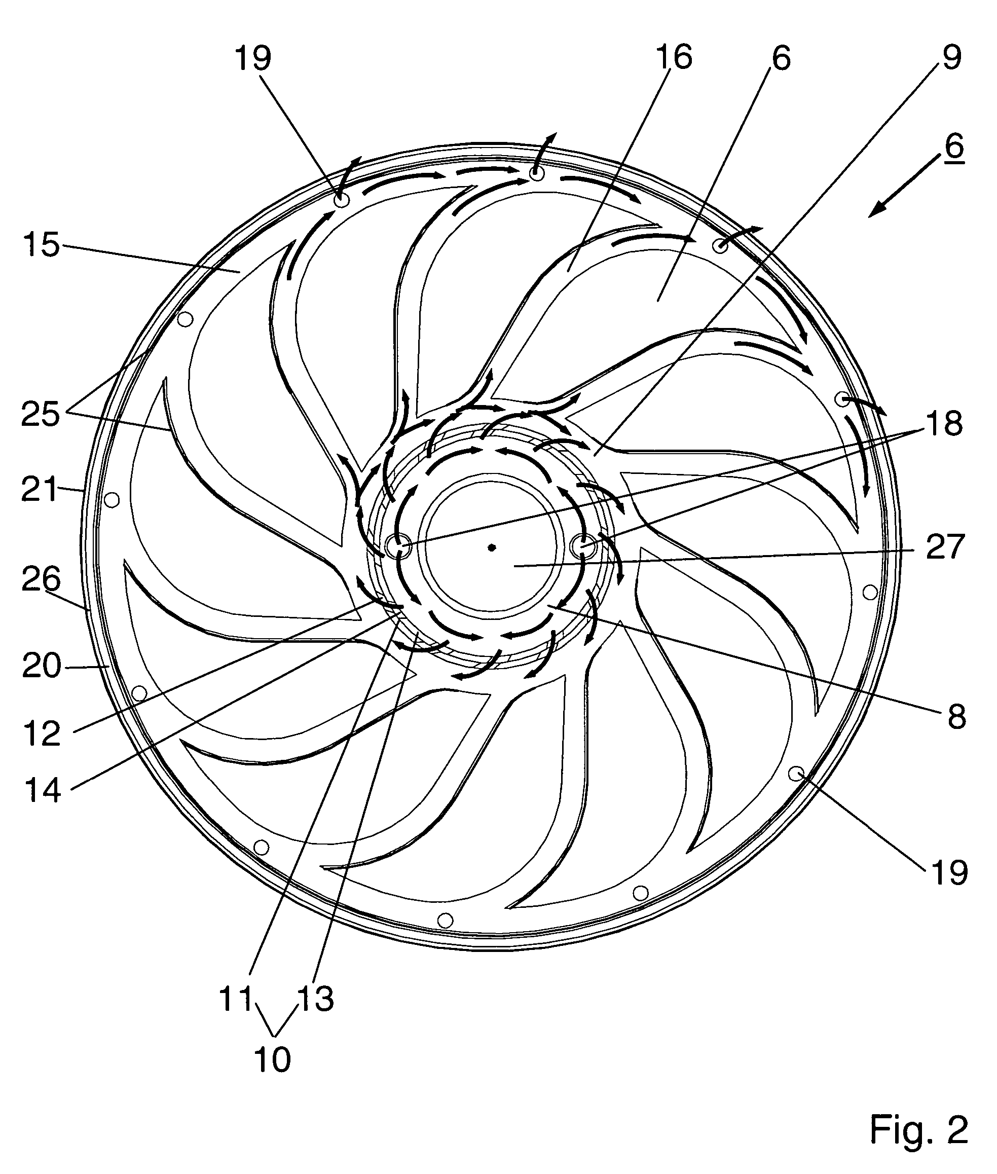
[0015]A one-piece blisk 1 for the compressor of an aircraft gas turbine comprises a disk 1′ with connecting arms 2 and a blade platform 3 with integral blade airfoils 4. For wear-protection coating of the blade airfoils 4 with carbides or nitrides or for heat treatment subsequent to blade repair, only the blade airfoils 4 are exposed to the temperature required for furnace heat treatment or vapor deposition, while the uncoated parts of the blisk 1 are heated to a temperature which does exceed the normal operating temperature of the aircraft gas turbine, but not a max. acceptable temperature of 320° C. or 350° C., as appropriate for the respective titanium alloy used, for example Ti64 or Ti6246. For this purpose, the blisks 1, with the exception of the blade airfoils 4, are accommodated or held in the cooling apparatus described in the following.

[0016]The cooling apparatus, shown here by way of example of two blisks to be heat-treated, comprises three cooling plates 5 to 7, actually ...


PUM

PropertyMeasurementUnit
temperatureaaaaaaaaaa

Abstract

A method for hard-material coating or heat treatment of the blade airfoils of blisks for gas turbines provides for partial heat-insulation and cooling of the other blisk parts during the respective process to prevent their properties from being changed by the high temperatures. The apparatus required for this method comprises two or more cooling plates (5 to 7) which are thermally insulated on their outer surfaces and include supporting flanges (20) which heat-conductively locate the blade platforms (3) of the blisks (1). Radially extending cooling medium channels (16) are provided in the cooling plates connected to a cooling medium source to continually apply cooling medium to the inner surfaces of the supporting flanges and the blade platforms.

Description

[0001]This application claims priority to German Patent Application DE10356679 filed Nov. 28, 2003, the entirety of which is incorporated by reference herein.BACKGROUND OF THE INVENTION[0002]This invention relates to a method for elevated-temperature hard-material coating or heat treatment of the blade airfoils of blisks of aircraft gas turbines and an apparatus for the performance of this method.[0003]High-pressure compressors of aircraft turbines can be equipped with blisks where the actual disk, the blade platforms and the blade airfoils are manufactured as one integral part. In order to improve protection against wear by particles carried by the compressed air, the blade airfoils, as is generally known, are coated, for example, by means of an elevated-temperature plasma vapor deposition process using hard materials, such as nitrides or carbides. Further, after repair of the blade airfoils, the blisks are subject to a heat-treatment process. The coating or the heat-treatment proc...

Claims


Application Information

Patent Timeline
Patent Type & Authority Patents(United States)
IPC IPC(8): C23C16/00C23C16/04C23C16/46C23C16/458C23C16/06C21D9/00C23C14/04
CPCC21D9/0025C21D9/0068C21D2221/00
Inventor MIELKE, RAINER
Owner ROLLS ROYCE DEUT LTD & CO KG
Why Eureka
Try Eureka