Light source device and image display device
A light source device and light beam technology, applied in the field of light sources, can solve the problems that the output brightness cannot meet the brightness requirements, the service life of the image display device is affected, and the transmittance and service life of optical elements are reduced.
- Summary
- Abstract
- Description
- Claims
- Application Information
AI Technical Summary
Problems solved by technology
Method used
Image
Examples
Embodiment 1
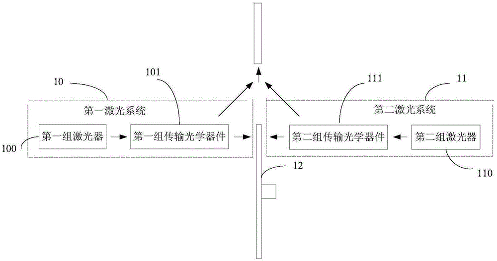
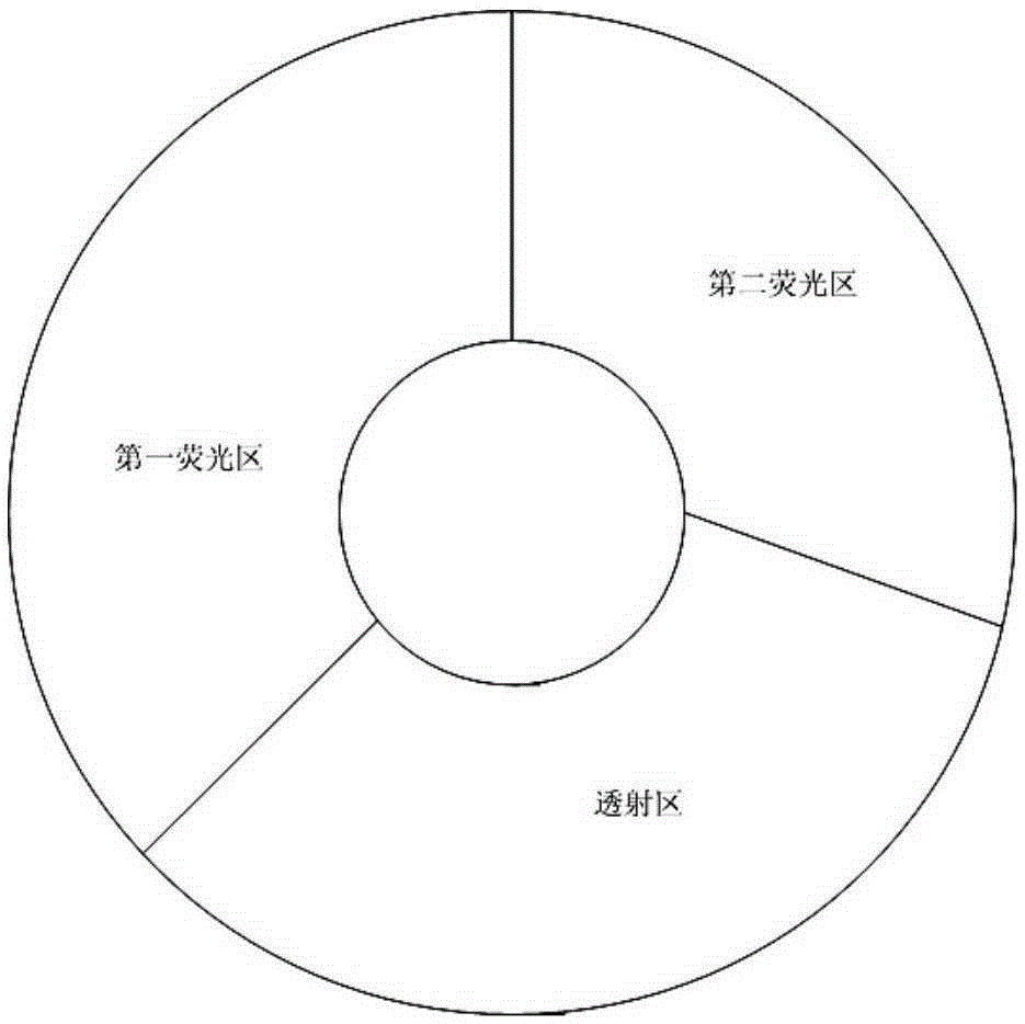
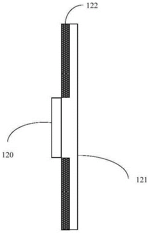
[0029] Figure 1A It is a schematic structural diagram of Embodiment 1 of the light source device of the present invention, such as Figure 1A As shown, the light source device includes: a first laser system 10, a second laser system 11, and a fluorescent wheel 12; the first laser system 10 includes: a first group of lasers 100 and a first group of transmission optical components 101; the second The laser system 11 includes: a second group of lasers 110 and a second group of transmission optical components 111 (optionally, each group of lasers may include: at least two lasers); the fluorescent wheel includes: a fluorescent area and a transmission area (optionally , the fluorescent wheel can be a transmissive fluorescent wheel; the fluorescent wheel is rotated by a centrally arranged motor); optionally, the first laser system 10 and the second laser system 11 are arranged on the fluorescent wheel 12 on both sides; the first polarized light beam produced by the first group of las...
Embodiment 2
[0039] Figure 2A It is a schematic structural diagram of Embodiment 2 of the light source device of the present invention. On the basis of the above embodiments, the first group of transmission optical components 101 includes: a first light-combining lens 101a; the second group of transmission optical components 111 includes: Two light-combining lenses 111a; wherein, a film for transmitting the first polarized light beam and reflecting the second polarized light beam is provided on the first surface of the first light-combining lens 101a close to the first group of lasers 100 layer, a film layer for transmitting the first polarized light beam and reflecting the first part of the light beam is provided on the second surface of the first light-combining lens 101a close to the fluorescent wheel 12; the second light-combining lens A film layer for transmitting the second polarized light beam and reflecting the first polarized light beam is provided on the third surface of 111a cl...
Embodiment 3
[0044] Figure 2C It is a structural schematic diagram of the third embodiment of the light source device of the present invention, in the above Figure 2A and Figure 2B On the basis of the above, the first set of transmission optical components 101 also includes: a first collimating lens group 101c, wherein the first collimating lens group 101c is arranged between the first light-combining lens 101a and the fluorescent wheel Between 12; the first collimating lens group 101c is used for: collimating the first polarized light beam passing through the first light-combining lens 101a, and directing it to the fluorescent wheel 12; because the fluorescent wheel The divergence angle of the generated first light beam is large and the directionality is uncertain, and the first collimating lens group 101c is also used for: combining the first part of the light beam and the second polarized light beam passing through the fluorescent wheel 12 collimate, and shoot to the first light-co...
PUM
 Abstract
Description
Claims
Application Information
 - R&D
- Intellectual Property
- Life Sciences
- Materials
- Tech Scout
- Unparalleled Data Quality
- Higher Quality Content
- 60% Fewer Hallucinations
Browse by: Latest US Patents, China's latest patents, Technical Efficacy Thesaurus, Application Domain, Technology Topic, Popular Technical Reports.
© 2025 PatSnap. All rights reserved.Legal|Privacy policy|Modern Slavery Act Transparency Statement|Sitemap|About US| Contact US: help@patsnap.com


