Liquid crystal panel and liquid crystal display device

Inactive Publication Date: 2012-08-30
PANASONIC LIQUID CRYSTAL DISPLAY CO LTD
View PDF3 Cites 28 Cited by
  • Summary
  • Abstract
  • Description
  • Claims
  • Application Information

AI Technical Summary

Benefits of technology

[0015]According to another aspect of the present invention, the retardation value of the liquid crystal layer in black display period maybe larger than the retardation value of the liquid crystal layer in white display period; and a difference between the retardation value of the liquid crystal layer in black display period and the retardation value of the liquid crystal layer in white display period is equal to or larger than 100 nm and equal to or smaller than 300 nm. According to this aspect of the present invention, sufficient white display can be obtained.
[0016]According

Problems solved by technology

In a case where the liquid crystal display device is used outdoors, not only light emitted through the liquid crystal panel from the backlight un

Method used


Image

  • Liquid crystal panel and liquid crystal display device
  • Liquid crystal panel and liquid crystal display device
  • Liquid crystal panel and liquid crystal display device

Examples


Embodiment Construction

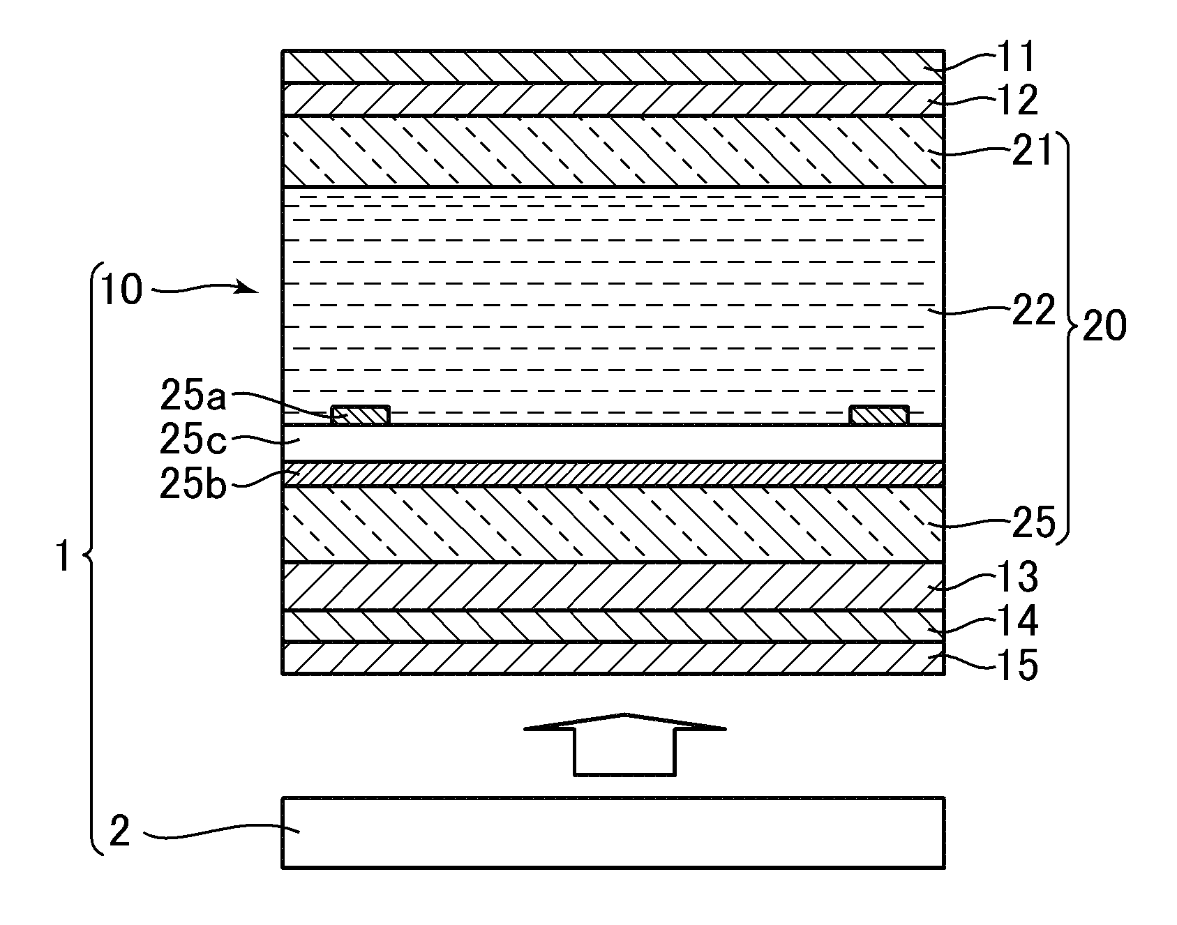
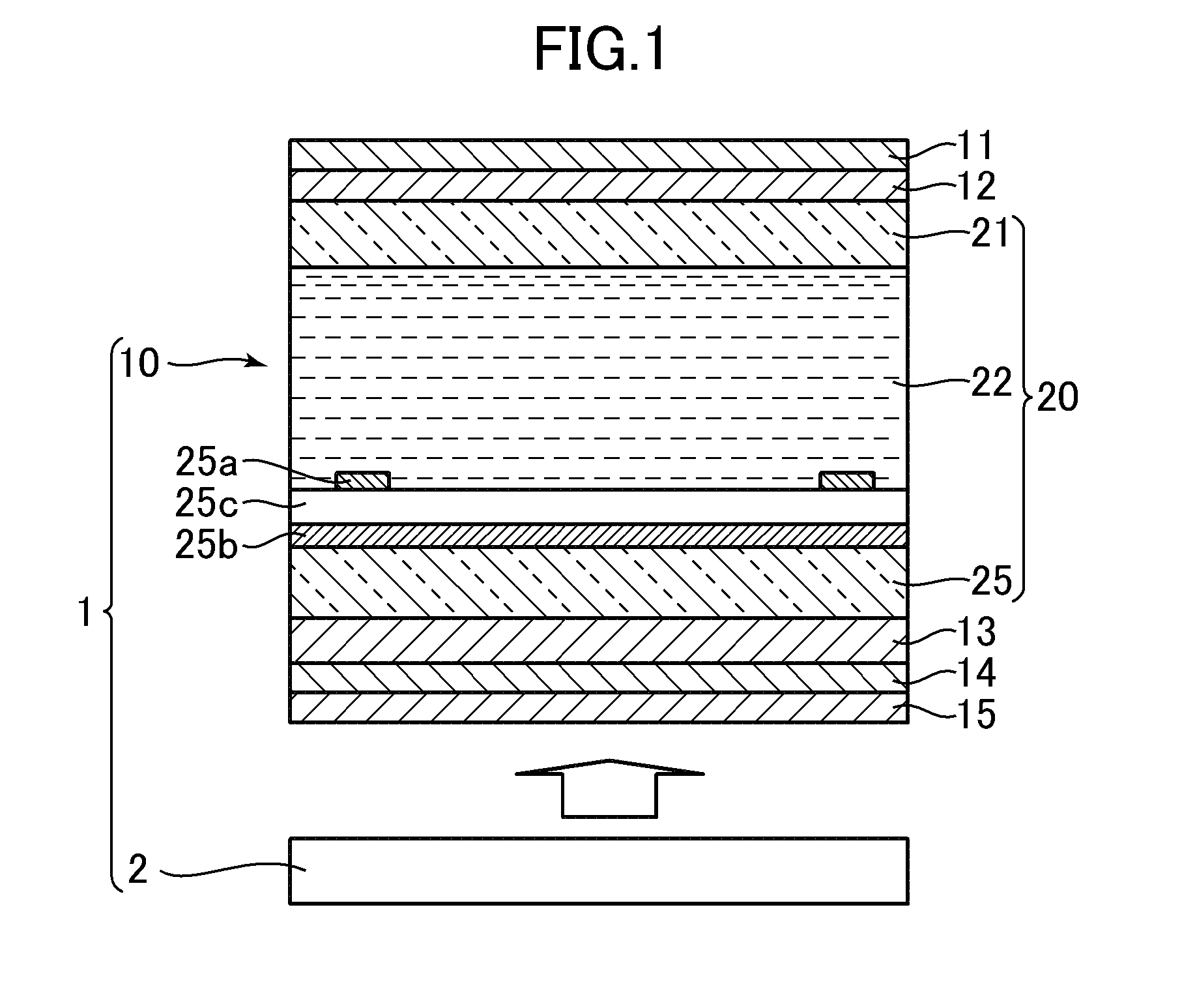
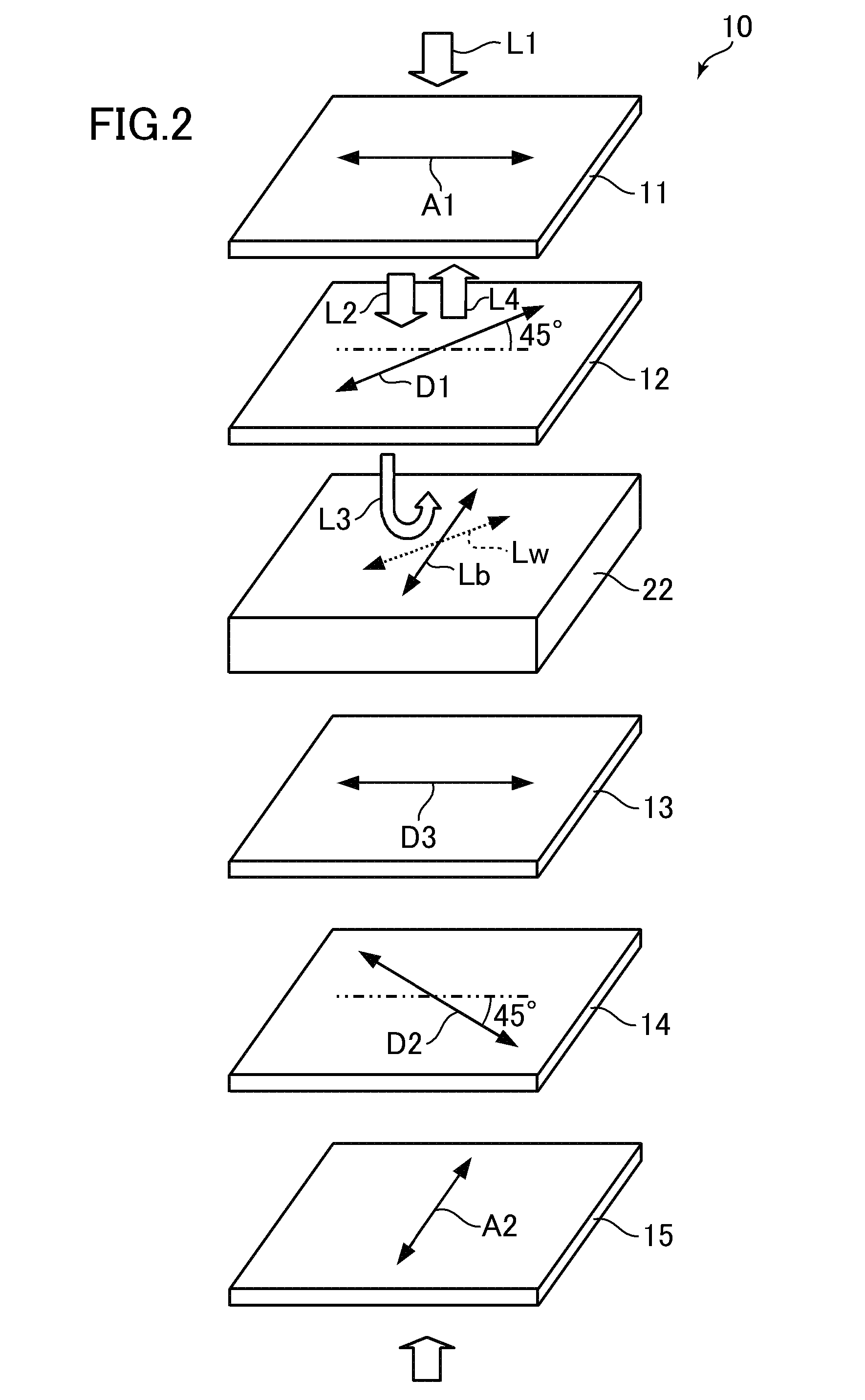
[0029]Hereinafter, an embodiment of the present invention is described with reference to the drawings. FIG. 1 is a sectional view schematically illustrating a structure of a liquid crystal display device 1 according to an embodiment of the present invention. FIG. 2 is a view illustrating a slow axis direction and an absorption axis direction of optical members forming a liquid crystal panel 10 of the liquid crystal display device 1.

[0030]As illustrated in FIG. 1, the liquid crystal display device 1 includes the liquid crystal panel 10 of in-plane switching (IPS) mode and a backlight unit 2 arranged on the back side of the liquid crystal panel 10. The liquid crystal panel 10 receives light applied on the back side thereof from the backlight unit 2.

[0031]The liquid crystal panel 10 includes a first polarizing plate 11 arranged on the front side thereof, and a second polarizing plate 15 arranged on the back side thereof. The first polarizing plate 11 and the second polarizing plate 15 ...


PUM


Abstract

A first retardation plate arranged on a front side causes light received through the a first polarizing plate from the front side to become close to circularly polarized light rotating in a first direction. Second and third retardation plates arranged on a back side cause light received through a second polarizing plate from the back side to become close to circularly polarized light rotating in a second direction opposite to the first direction while passing through both of the second and third retardation plates and the liquid crystal layer in black display period. With this structure, good image quality can be obtained even when used in outdoor.

Description

CROSS-REFERENCE TO RELATED APPLICATION[0001]The present application claims priority from Japanese application JP 2011-037928 filed on Feb. 24, 2011, the content of which is hereby incorporated by reference into this application.BACKGROUND OF THE INVENTION[0002]1. Field of the Invention[0003]The present invention relates to a liquid crystal panel of in-plane switching (IPS) mode which received light from a backlight unit, and more particularly, to a technology for reducing the outside light influence on image quality.[0004]2. Description of the Related Art[0005]There has been used a liquid crystal panel of in-plane switching (IPS) mode in which a pixel electrode and a common electrode are both formed on at least one substrate of two transparent substrates sandwiching a liquid crystal layer (for example, Japanese Patent Application Laid-open No. 2011-017834). The image quality of the liquid crystal panel of this mode is less dependent on the viewing direction of the liquid crystal pan...

Claims


Application Information

Patent Timeline
IPC IPC(8): G02F1/1335
CPCG02F1/134363G02F2413/03G02F2001/133638G02F2001/133541G02F1/133541G02F1/133638
Inventor KAJITA, DAISUKE
Owner PANASONIC LIQUID CRYSTAL DISPLAY CO LTD
Why Eureka
Try Eureka