
Vertical alignment mode liquid crystal display

a liquid crystal display and vertical alignment technology, applied in the field of vertical alignment mode, can solve the problems of reduced contrast, reduced contrast, and insufficient effect, and achieve the effects of increasing and avoiding the effect of reducing the thickness of the liquid crystal display

Inactive Publication Date: 2015-07-14
KONICA MINOLTA OPTO
View PDF17 Cites 0 Cited by
  • Summary
  • Abstract
  • Description
  • Claims
  • Application Information

AI Technical Summary

Benefits of technology

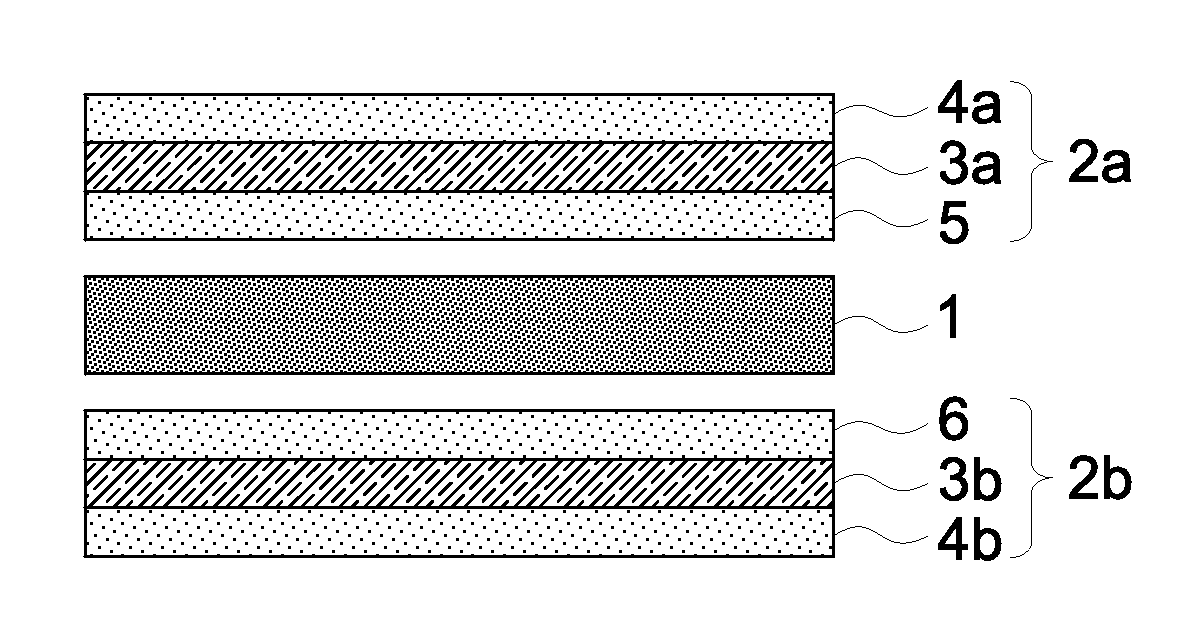
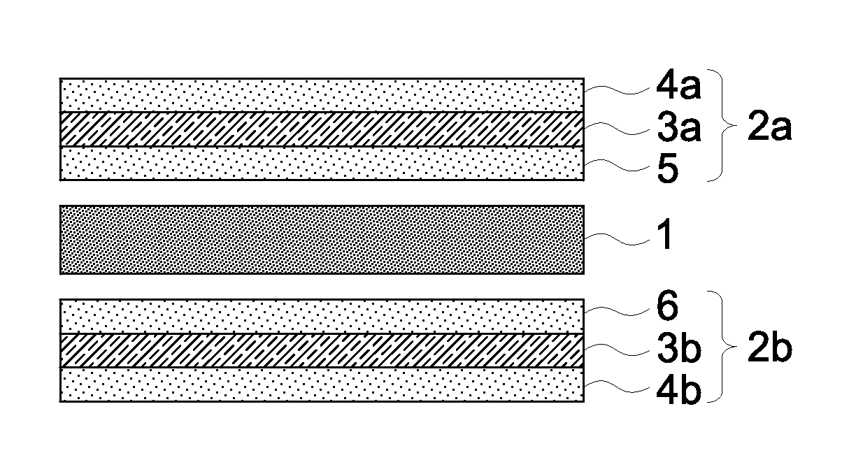
[0020]According to the VA mode liquid crystal display of the present invention, it becomes possible to provide retardation necessary to compensate an apparent misalignment of the axes of the polarizers in a VA mode liquid crystal display and the retardation of the liquid crystal layer used in the liquid crystal cell without making the manufacturing process more complicated or increasing the thickness of the liquid crystal display by employing optically biaxial optical films each having an individual in-plane retardation and a retardation in the thickness direction.
[0021]Further, in an above aspect of the present invention, the in-plane retardation values (Ro values) and the retardation values in the thickness direction (Rth values) of a first optical film and a second optical film which are biaxial films are so constructed that the in-plane retardation value of the first optical film is larger than that of the second optical film, and the retardation value in the thickness direction of the second optical film is larger than that of the first optical film. Namely, the in-plane retardation value is disproportionately provided so that the retardation value of the first optical film is larger, and the retardation value in the thickness direction is disproportionately provided so that the retardation value of the second optical film is larger. Further, the wavelength dispersion of the in-plane retardation value of the first optical film is constructed to be smaller that the wavelength dispersion of that of the second optical film, and the wavelength dispersion of the retardation value in the thickness direction of the second optical film is constructed to be larger that the wavelength dispersion of that of the first optical film. Thus, in the liquid crystal display of the present invention, it is possible to control the in-plane retardation values and the retardation values in the thickness direction to have more preferable wavelength dispersion properties, because, when viewed as a whole, the first optical film is dominant with respect to the wavelength dispersion of the in-plane retardation value and the second optical film is dominant with respect to the wavelength dispersion of the retardation value in the thickness direction, since the in-plane retardation values and the retardation values in the thickness direction are individually disproportionately provided to the first optical film and the second optical film which are biaxial films, whereby the wavelength dispersion of the in-plane retardation value and the wavelength dispersion of the retardation value in the thickness direction are provided in different ways. Namely, wavelength dispersion properties suitable to compensate an apparent misalignment of the axes of the polarizers and the retardation value in the thickness direction of the liquid crystal cell in all over the visible light region can be provided.
[0022]As the results, the coloration which occurs in a black display due to light leakage can be suppressed and a VA mode liquid crystal display exhibiting excellent front contrast, and excellent properties regarding color shift and a viewing angle, when viewed from an oblique direction, can be provided. Further, by using two biaxial optical films which also have a function of a polarizing plate protective film, the manufacturing process can be made more simple without increasing the thickness of the liquid crystal display.

Problems solved by technology

However, the vertical alignment mode liquid crystal display has a problem that coloring in a black display due to light leakage, or reduced contrast is observed when the display is viewed from an oblique direction.
Although the above disclosed optical compensation films are effective to compensate retardation for a specified wavelength of light, the effect is not fully enough for light of a wavelength other than the specified wavelength and, also, there has been a problem that coloring in a black display due to light leakage, or reduced contrast is observed when the display is viewed from an oblique direction.
However, it is very difficult to produce an optically uniaxial optical compensation film as described above employing a resin material commonly used for a polarizing plate protective film, such as a cellulose ester film, and it is necessary to use a material having a large photoelastic coefficient to produce a uniaxial film using a resin.
Therefore, unevenness in a retardation value tends to occur, and as the results, suppression of light leakage in an oblique direction becomes difficult.
A uniaxial film formed from such a material generally exhibits poor adhesion with a polyvinylalcohol resin commonly used as a polarizer, and it tend to be difficult to directly adhere with such a polarizer, and, when it is directly adhered with a polarizer, unevenness in retardation tends to occur, which also results in occurrence of light leakage.
Accordingly, a conventionally used polarizing plate protective film has also been necessary between a uniaxial film and a polarizer, which has been a problem because of increase in the thickness of a liquid crystal display and a manufacturing cost.
However, this technique also results in problems, for example, a thicker liquid crystal display panel and a higher manufacturing cost due to a complicated manufacturing process.
However, it has been difficult to obtain a single biaxial resin film which enables sufficient optical compensation of a VA mode liquid crystal display apparatus.
However, according to the technique disclosed in Patent Document 6, there has been a problem that the in-plane retardation and the retardation in the thickness direction have similar features in wavelength dispersion, since the optical compensation is carried out by using the in-plane retardation and the retardation in the thickness direction exhibited by each of the two biaxial optical compensation films.
Namely, while mutually different wavelength dispersions are necessary to compensate the apparent misalignment of the axes and the retardation in the thickness direction of a liquid crystal cell in all over the visible light region, faced has been a problem that it is difficult to independently control the in-plane retardation value and the retardation value in the thickness direction.
For example, when the in-plane retardation is controlled to show reverse wavelength dispersion in order to compensate the apparent misalignment of the axes of the polarizers, the retardation in the thickness direction also shows reverse wavelength dispersion, which is contrary to the desired wavelength dispersion for the for the retardation of the liquid crystal layer of the liquid crystal cell, whereby compensation over a wide wavelength range becomes difficult.
Alternatively, when the retardation in the thickness direction is controlled to show flat or normal wavelength dispersion, the in-plane retardation also shows similar wavelength dispersion, whereby compensation of the misalignment of the axes over a wide wavelength range becomes difficult.
Thus, it has been difficult to effectively compensate the apparent misalignment of the axes of the polarizers and the retardation in the thickness direction of the liquid crystal layer used in a liquid crystal cell in all over the visible light region.

Method used


Image

  • Vertical alignment mode liquid crystal display
  • Vertical alignment mode liquid crystal display
  • Vertical alignment mode liquid crystal display

Examples


examples

[0229]The present invention will be explained below with referring to examples, however, the present invention is not limited thereto.

101-104>

1>

[0230]

Particles (AEROSIL R972V, manufactured by11 parts by massNippon Aerosil Co., Ltd.)Ethanol89 parts by mass

These were mixed and agitated for 50 minutes by means of dissolver and then dispersed by Manton-Gaurin.

[0231]Particle dispersion liquid 1 was added slowly in a dissolution tank charged with methylene chloride while sufficiently agitating. Dispersion was carried out by an attritor mill so that particle diameter of secondary particles reached to a predetermined size. The resultant was filtered by FINEMET NT manufactured by Nippon seisen Co. Ltd, and Microparticles addition liquid 1 for in-line addition was obtained.

1>

[0232]

Methylene chloride99 parts by massParticle dispersion liquid 1 5 parts by mass

[0233]Main dope liquid 1 of the following composition was prepared. First, methylene chloride and ethanol were added to a pressure dissol...


PUM

PropertyMeasurementUnit
thicknessaaaaaaaaaa
wavelengthsaaaaaaaaaa

Abstract

A vertical alignment mode liquid crystal display comprising: a liquid crystal cell; a first polarizer; a second polarizer; a first optical film arranged between the first polarizer and the liquid crystal cell; and a second optical film arranged between the liquid crystal cell and the second optical film, wherein the first and the second optical films each are a resin film having an optically biaxial property, the first and the second optical films meet: Formula (1) Ro1>Ro2; Formula (2) Rth1<Rth2; Formula (3) DSPRo1<DSPRo2; and Formula (4) DSPRth1<DSPRth, wherein Ro1 and Ro2 represent in-plane retardation values of the first and the second optical films, respectively, Rth1 and Rth2 represent retardation values in the thickness direction of the first and the second optical films, respectively, and DSPRo1, DSPRo2, DSPRth1 and DSPRth2 represent wavelength dispersion properties of Ro1, Ro2; Rth1 and Rth2, respectively.

Description

CROSS REFERENCE TO RELATED APPLICATION[0001]This is a 371 of PCT / JP2010 / 052049 filed Feb. 12, 2010, which in turn claimed the priority of Japanese Patent Application No. 2009-066238 filed Mar. 18, 2009, both of the applications are incorporated by reference herein.FIELD OF THE INVENTION[0002]The present invention relates to a vertical alignment mode (hereafter, abbreviated to a VA mode) liquid crystal display, and, in more detail, relates to a VA mode liquid crystal display in which coloring which occurs in a black display due to light leakage is suppressed, and excellent front contrast, and excellent properties regarding color shift and viewing angle are achieved.BACKGROUND ART[0003]Needs for liquid crystal displays for the application to such as an LCD television and a personal computer display have expanded. Usually, a liquid crystal display is constituted of a liquid crystal cell formed by sandwiching transparent electrodes, a liquid crystal layer, a color filter and so on with ...

Claims


Application Information

Patent Timeline
Patent Type & Authority Patents(United States)
IPC IPC(8): G02F1/13363G02B5/30G02F1/1337
CPCG02F1/133634G02B5/3083G02F2001/133637G02F2001/133742G02F2202/40G02F2413/02G02F2413/12G02F1/133637G02F1/133742G02B5/30G02F1/1335G02F1/13363G02F2413/05
Inventor YANO, KENTAROOKA, SHIGEKIINAGAKI, AYAKOKANEKO, YUKI
Owner KONICA MINOLTA OPTO
Learn More