Optical head device

a head device and optical technology, applied in the field of optical head devices, can solve the problems of insufficient high-light utilization efficiency, inability to obtain desired characteristics, and inability to meet the requirements of high-recording-density use, and achieve the effects of reducing the number of components, shortening assembly time, and small siz

Inactive Publication Date: 2011-07-26
ASAHI GLASS CO LTD
View PDF11 Cites 0 Cited by
  • Summary
  • Abstract
  • Description
  • Claims
  • Application Information

AI Technical Summary

Benefits of technology

[0027]According to the present invention, differently from conventional optical head devices, a phase plate having a retardation value which decreases as the wavelength becomes shorter, is employed for at least one of two broadband phase plates laminated together. The phase plate substantially functions as a quarter wavelength plate for at least three linearly polarized laser beams having different wavelengths transmitted, and transforms the linearly polarized laser beams into circularly polarized laser beams. This feature enables to make an optical element common to the wavelengths to reduce the number of components, and realizes an optical head device requiring shorter assembly time, which is small sized and low cost.

Problems solved by technology

However, a phase plate (quarter wavelength plate) for converting linearly polarized light beams of two wavelengths such as wavelengths 405 nm and 660 nm, to circularly polarized light beams, cannot convert a linearly polarized light beam of wavelength 790 nm to a complete circularly polarized light beam.
In the same manner, a phase plate for converting linearly polarized light beams of wavelengths 660 nm and 790 nm to circularly polarized light beams, cannot convert a linearly polarized light beam of 405 nm to a complete circularly polarized light beam, and thus, desired characteristics cannot be obtained.
However, in order to obtain a function of complete quarter wavelength plate in entire region of wavelength from 400 to 780 nm by using the single broadband phase plate, design of the material is extremely difficult and such a broadband phase plate is not satisfactory for high-recording-density use which requires high-light-utilization efficiency.
Further, hereinafter, in an optical head device to be used for an optical recording medium for which higher light-utilization efficiency is required such as a Blu-Ray Disk that is expected to be a next-generation standard which uses a light source of further shorter wavelength, optical elements such as the above-mentioned quarter wavelength plate do not have sufficient characteristics.
For example, in an optical head device using three wavelengths 405 nm, 660 nm and 790 nm, it is necessary to dispose total three sets of optical elements that are optical elements for 405 nm, optical elements for 660 nm and optical element for 790 nm, which causes problems that the number of components is increased to increase the volume of the device and that it takes longer time for assembly and adjustment.
However, in these cases, it is difficult to switch optical paths for respective wavelengths even by using a beam splitter having different reflectivities at different wavelengths.

Method used


Image

  • Optical head device
  • Optical head device
  • Optical head device

Examples


example 1

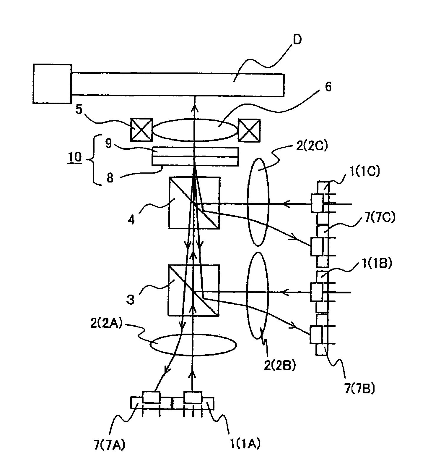
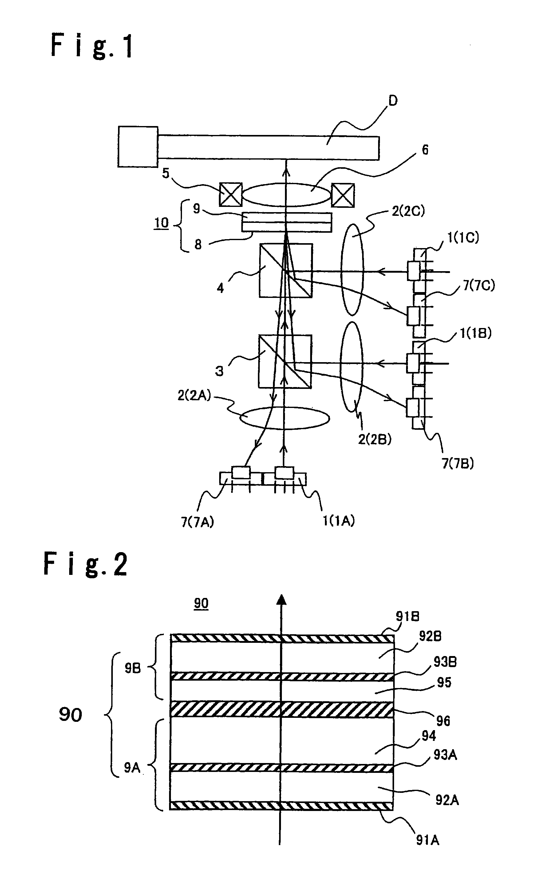
[0113]This Example is described with reference to FIG. 2.

[0114]As shown in FIG. 2, a broadband phase plate 90 of this Example is constituted by first and second phase plates 9A and 9B that are integrated together.

[0115]Specifically, a glass substrate 92A is prepared which is a transparent substrate having a diameter of 12.5 cm and a thickness of 0.5 mm whose one of surfaces (lower surface in the Figure) in which laser beams are incident is provided with a low reflective coating film 91A. On a surface of the glass substrate 92A (upper surface in the Figure) opposite from the light source 1 (refer to FIG. 1), a polyimide film is formed and applied with horizontal alignment treatment by rubbing to form a polyimide film 93A. On the glass substrate 92A applied with the alignment treatment, SiO2 beads (not shown) of 6.6 μm in diameter is dispersed at a density of 5,000 pieces / cm2 in order to maintain a gap between the substrate and a surface of a glass substrate 92B being a transparent su...

example 2

[0130]In Example 2, a case of employing two types of liquid crystal monomers as materials having extraordinary dispersion property, is described.

[0131]As the two types of liquid crystal monomers, a liquid crystal monomer which produces an organic thin film having a birefringence of 0.0361 at a wavelength 405 nm, 0.0473 at a wavelength 660 nm and 0.0500 at a wavelength 790 nm, and a liquid crystal monomer which produces an organic thin film having a birefringence of 0.0194 at a wavelength 405 nm, 0.0239 at a wavelength 660 nm and 0.0250 at a wavelength 790 nm, are employed.

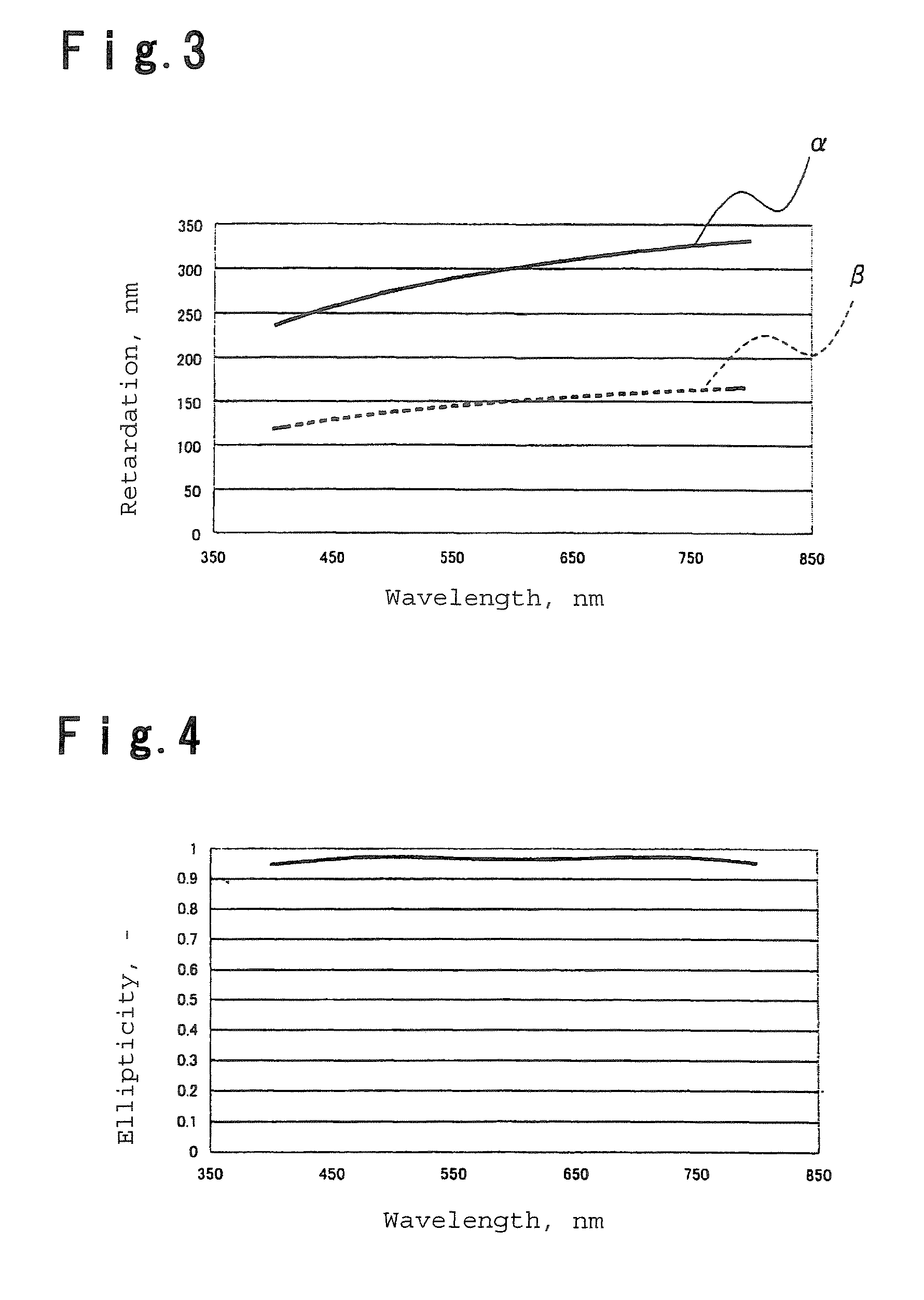
[0132]By using these liquid crystal monomers, a broadband phase plate is produced by a method equivalent to that of Example 1. At this time, the thickness of the first phase plate in the light-incident side is 6.6 μm, the thickness of the second phase plate in the light-output side is 6.3 μm, and these phase plates are disposed so that the crossing angle of their optical axes becomes 61°. The retardation values of ...

example 3

[0134]The following compound (1A), the following compound (1B), the following compound (1C) and the following compound (1U) are mixed at a molar ratio of 6:8:6:5 to obtain a liquid crystal composition A. When an organic thin film was formed by using the liquid crystal composition A, the birefringent index was 0.0065 at wavelength 405 nm, 0.0105 at wavelength 660 nm and 0.0107 at wavelength 790 nm.

[0135]When R(λ) / λ at the wavelengths are calculated from these values, the ratio of those of wavelength 405 nm, 660 nm and 790 nm becomes 1.65:1.59:1.35, which shows that R(λ) / λ decreases as the wavelength increases. Namely, this shows that the increase rate of retardation value is smaller than the increase rate of wavelength.

[0136]

[0137]By using this liquid crystal composition A, a broadband phase plate is produced by a method equivalent to that of Example 1. At this time, the thickness of the first phase plate in the light-incident side is 31.5 μm, the thickness of the second phase plate ...


PUM

PropertyMeasurementUnit
crossing angleaaaaaaaaaa
wavelengthaaaaaaaaaa

Abstract

An optical head device having a broadband phase plate of transforming at least three linearly polarized light beams having different wavelengths into circularly polarized light beams, is obtained.A broadband phase plate comprising two phase plates 9A and 9B laminated with e.g. an adhesive agent so that their optical axes are crossed, wherein provided that wavelengths of linearly polarized incident light beams are λ1, λ2 and λ3 (λ1<λ2<λ3), at least one or both of the two phase plates has such a phase difference characteristics that a ratio R(λ1) / R(λ3) and a ratio R(λ2) / R(λ3) between retardation values of the wavelengths are smaller than 1 and R(λ1) / R(λ3) is smaller than R(λ2) / R(λ3), is integrated in the optical head device.

Description

TECHNICAL FIELD[0001]The present invention relates to an optical head device employing a broadband phase plate for controlling phase state of laser beam.BACKGROUND ART[0002]An optical head device is employed for writing an optical information to or reading an optical information from an optical recording medium such as an optical disk or an optical magnetic disk. In such an optical head device, emission light from a laser diode as a light source, is converged by an objective lens on a recording plane of a disk-shaped optical recording medium (hereinafter referred to as “optical disk”), to carry out writing and / or reading of an information. At a time of e.g. reading an information, emission light reflected by an information recording plane of an optical disk is received by a photodetector.[0003]By the way, with respect to read-out of information, the shorter the wavelength of laser beam in use is, the more the recording density can be increased, and thus, use of emission light of sho...

Claims


Application Information

Patent Timeline
Patent Type & Authority Patents(United States)
IPC IPC(8): G11B7/00G11B7/135
CPCG02B5/3083G11B7/1365G11B7/1369G11B2007/0006
Inventor TAKESHITA, NOBUHIKOGUNJIMA, TOMOKIYOSHIDA, KARA
Owner ASAHI GLASS CO LTD
Why Eureka
Try Eureka