Transmission method and transmission apparatus

a transmission apparatus and transmission method technology, applied in the direction of digital transmission, transmission path sub-channel allocation, baseband system details, etc., can solve the problems of “degradation of reception quality, high field strength, and and achieve the effect of deterioration of reception quality

Active Publication Date: 2012-08-30
SUN PATENT TRUST
View PDF5 Cites 176 Cited by
  • Summary
  • Abstract
  • Description
  • Claims
  • Application Information

AI Technical Summary

Benefits of technology

[0049]With the above structure, the present invention provides a transmission method, a reception method, a transmission device, and a reception device that remedy degradation of reception quality in an LOS environment, thereby providing high-quality service to LOS users during broadcast or multicast communication.

Problems solved by technology

However, depending on the transmission system (for example, spatial multiplexing MIMO system), a problem occurs in that the reception quality deteriorates as the Rician factor increases (see Non-Patent Literature 3).
It is thus clear that the unique problem of “degradation of reception quality upon stabilization of the propagation environment in the spatial multiplexing MIMO system”, which does not exist in a conventional single modulation signal transmission system, occurs in the spatial multiplexing MIMO system.
When using a spatial multiplexing MIMO system having the above problem for broadcast or multicast communication, a situation may occur in which the received electric field strength is high at the reception device, but degradation in reception quality makes it impossible to receive the service.
Non-Patent Literature 8 does not at all disclose, however, a method for precoding in an environment in which feedback information cannot be acquired from the communication partner, such as in the above broadcast or multicast communication.
Non-Patent Literature 4 discloses using a unitary matrix as the matrix for precoding and switching the unitary matrix at random but does not at all disclose a method applicable to degradation of reception quality in the above-described LOS environment.

Method used


Image

  • Transmission method and transmission apparatus
  • Transmission method and transmission apparatus
  • Transmission method and transmission apparatus

Examples


embodiment 1

[0161]The following describes the transmission method, transmission device, reception method, and reception device of the present embodiment.

[0162]Prior to describing the present embodiment, an overview is provided of a transmission method and decoding method in a conventional spatial multiplexing MIMO system.

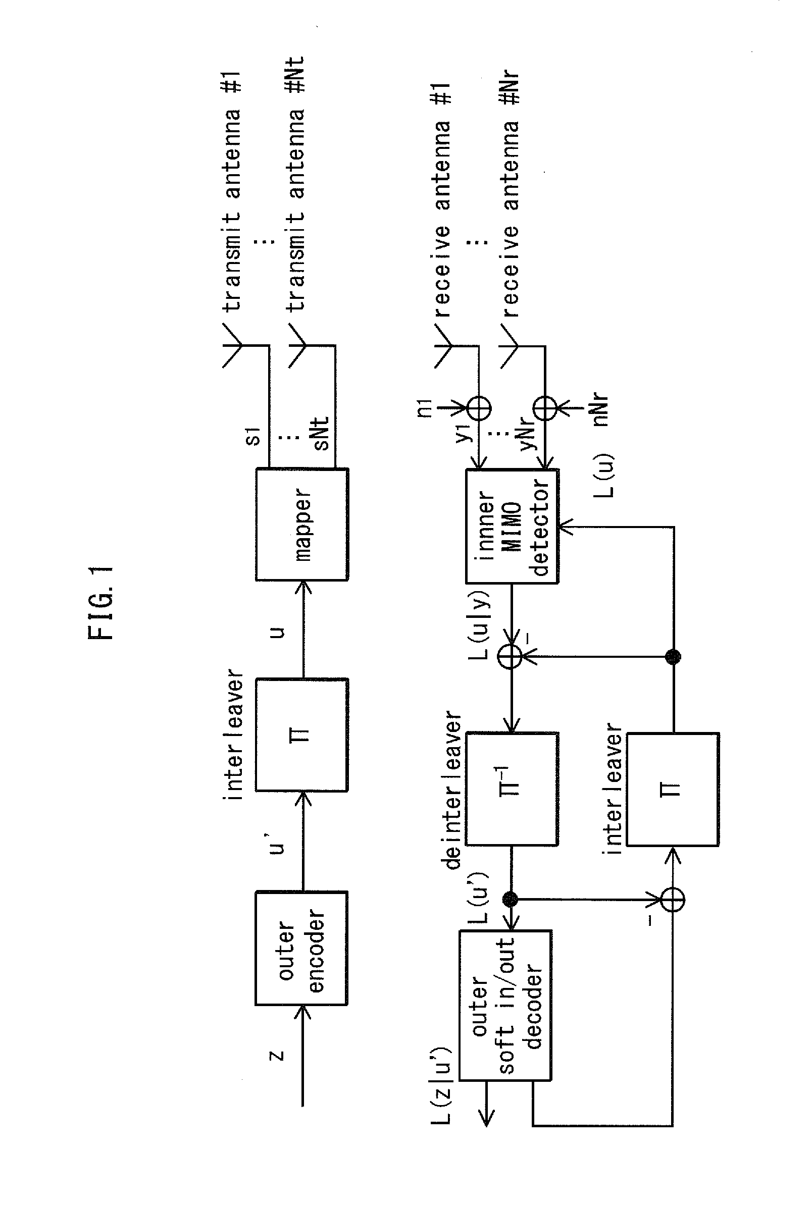
[0163]FIG. 1 shows the structure of an Nt×Nr spatial multiplexing MIMO system. An information vector z is encoded and interleaved. As output of the interleaving, an encoded bit vector u=(u1, . . . , uNt) is acquired. Note that ui=(ui1, . . . , uiM) (where M is the number of transmission bits per symbol). Letting the transmission vector s=(s1, . . . , sNt)T and the transmission signal from transmit antenna #1 be represented as si=map(ui), the normalized transmission energy is represented as E{∥si|2}=Es / Nt (Es being the total energy per channel). Furthermore, letting the received vector be y=(y1, . . . , yNr)T, the received vector is represented as in Equation 1.

Math1y=(y1,…,yNr)...

embodiment 2

[0301]In Embodiment 1, regular hopping of the precoding weights as shown in FIG. 6 has been described. In the present embodiment, a method for designing specific precoding weights that differ from the precoding weights in FIG. 6 is described.

[0302]In FIG. 6, the method for hopping between the precoding weights in Equations 37-40 has been described. By generalizing this method, the precoding weights may be changed as follows. (The hopping period (cycle) for the precoding weights has four slots, and Equations are listed similarly to Equations 37-40.) For symbol number 4i (where i is an integer greater than or equal to zero):

Equation42(z1(4i)z2(4i3))=12(jθ11(4i)j(θ21(4i)+λ)jθ21(4i)j(θ21(4i)+λ+δ))(s1(4i)s2(4i))Math42

Here, j is an imaginary unit.

For symbol number 4i+1:

Math43(z1(4i+1)z2(4i+1))=12(jθ11(4i+1)j(θ11(4i+1)+λ)jθ21(4i+1)j(θ21(4i+1)+λ+δ))(s1(4i+1)s2(4i+1))Equation43

For symbol number 4i+2:

Math44(z1(4i+2)z2(4i+2))=12(jθ11(4i+2)j(θ11(4i+2)+λ)jθ21(4i+2)j(θ21(4i+2)+λ+δ))(s1(4i+2)s2(4i...

example # 1

Example #1

[0307](1) θ11(4i)=θ11(4i+1)=θ11(4i+2)=θ11(4i+3)=0 radians,

(2) θ21(4i)=0 radians,

(3) θ21(4i+1)=π / 2 radians,

(4) θ21(4i+2)=π radians, and

(5) θ21(4i+3)=3π / 2 radians.

(The above is an example. It suffices for one each of zero radians, π / 2 radians, π radians, and 3π / 2 radians to exist for the set (θ21(4i), θ21(4i+1), θ21(4i+2), θ21(4i+3)).) In this case, in particular under condition (1), there is no need to perform signal processing (rotation processing) on the baseband signal S1(t), which therefore offers the advantage of a reduction in circuit size. Another example is to set values as follows.


PUM


Abstract

All data symbols used in data transmission of a modulated signal are precoded by switching between precoding matrices so that the precoding matrix used to precode each data symbol and the precoding matrices used to precode data symbols that are adjacent to the data symbol along the frequency axis and the time axis all differ. A modulated signal with such data symbols arranged therein is transmitted.

Description

CROSS-REFERENCE TO RELATED APPLICATION[0001]The disclosure of Japanese Patent Application No. 2010-043181 filed on Feb. 28, 2011, including the claims, specification, drawings, and abstract thereof, is incorporated herein by reference in its entirety.BACKGROUND OF THE INVENTION[0002](1) Field of the Invention[0003]The present invention relates to a precoding method, a precoding device, a transmission method, a transmission device, a reception method, and a reception device that in particular perform communication using a multi-antenna.[0004](2) Description of the Related Art[0005]Multiple-Input Multiple-Output (MIMO) is a conventional example of a communication method using a multi-antenna. In multi-antenna communication, of which MIMO is representative, multiple transmission signals are each modulated, and each modulated signal is transmitted from a different antenna simultaneously in order to increase the transmission speed of data.[0006]FIG. 28 shows an example of the structure o...

Claims


Application Information

Patent Timeline
Patent Type & Authority Applications(United States)
IPC IPC(8): H04L25/49
CPCH04L5/0023H04L5/0048H04L25/0204H04L25/0222H04L25/0242H04B7/0456H04L25/067H04L27/2604H04L1/005H04L1/0643H04L25/03942
Inventor MURAKAMI, YUTAKAKIMURA, TOMOHIROOUCHI, MIKIHIRO
Owner SUN PATENT TRUST
Why Eureka
Try Eureka