Speaker retaining mechanism and television receiver comprising same

a technology of retaining mechanism and television receiver, which is applied in the direction of transducer details, electrical transducers, electrical apparatus, etc., can solve the problems of image color shift, obstacle to a design having a thinner thickness, resonance sound by vibration also an obstacle to developing a television receiver having a higher sound quality

Active Publication Date: 2012-08-30
PANASONIC CORP
View PDF6 Cites 27 Cited by
  • Summary
  • Abstract
  • Description
  • Claims
  • Application Information

AI Technical Summary

Problems solved by technology

Regarding a Cathode Ray Tube (CRT)-type television receiver, a problem has been reported in which the speaker vibration causes the vibration of a shadow mask in the CRT via a cabinet to consequently cause an image having a color shift, for example.
This gives a more strict specification regarding to small space and small clearance design, resulting in an obstacle against a design having a thinner thickness.
Furthermore, the resonance sound by the vibration is also an obstacle for developing a television receiver having a higher sound quality.
However, when considering the vibration damping member disclosed in Publication 1 to be substituted with the vibration damping member having a reduced hardness disclosed in Publication 2, the stability of the speaker retention reduces as the hardness of the vibration damping member reduces, and this limits the reduction of the hardness.
Specifically, regarding the configuration as disclosed in Publication 1, the hardness of the vibration damping member is limited to about 20 degrees, and when the hardness is 10 degrees or less, it cannot provide a stable retention of the speaker.
Further, when a vibration damping member having a hardness of 10 degrees or less is used, it is even difficult to insert the vibration damping member to a boss.
Therefore, the combination of techniques disclosed in Publications 1 and 2 is insufficient to provide a sufficient vibration damping effect.
A vibration damping member having a low hardness also may cause an unstable speaker retention, due to a significant deformation of the vibration damping member itself, caused by the weight of the speaker.
This gives a variation in the speaker position Thus, it is difficult to form a baffle face on the front face of the speaker completely, thus failing to provide reproduction having a stable sound quality.

Method used


Image

  • Speaker retaining mechanism and television receiver comprising same
  • Speaker retaining mechanism and television receiver comprising same
  • Speaker retaining mechanism and television receiver comprising same

Examples


first embodiment

[0025]First Embodiment is an example in which a speaker retaining mechanism of the present invention is applied in a television receiver.

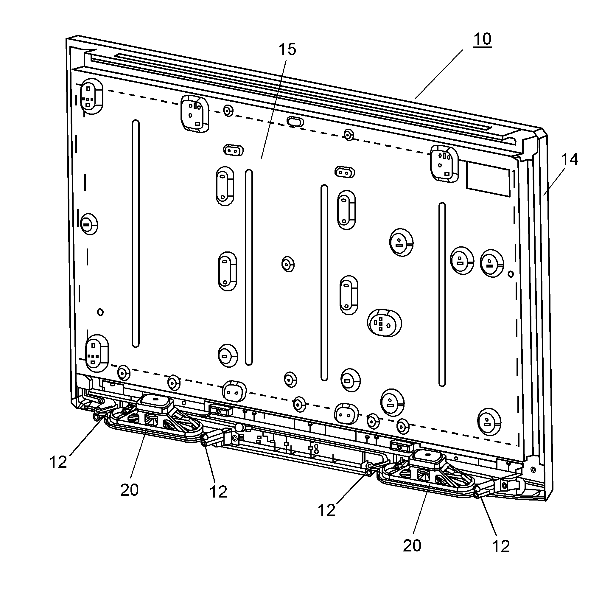
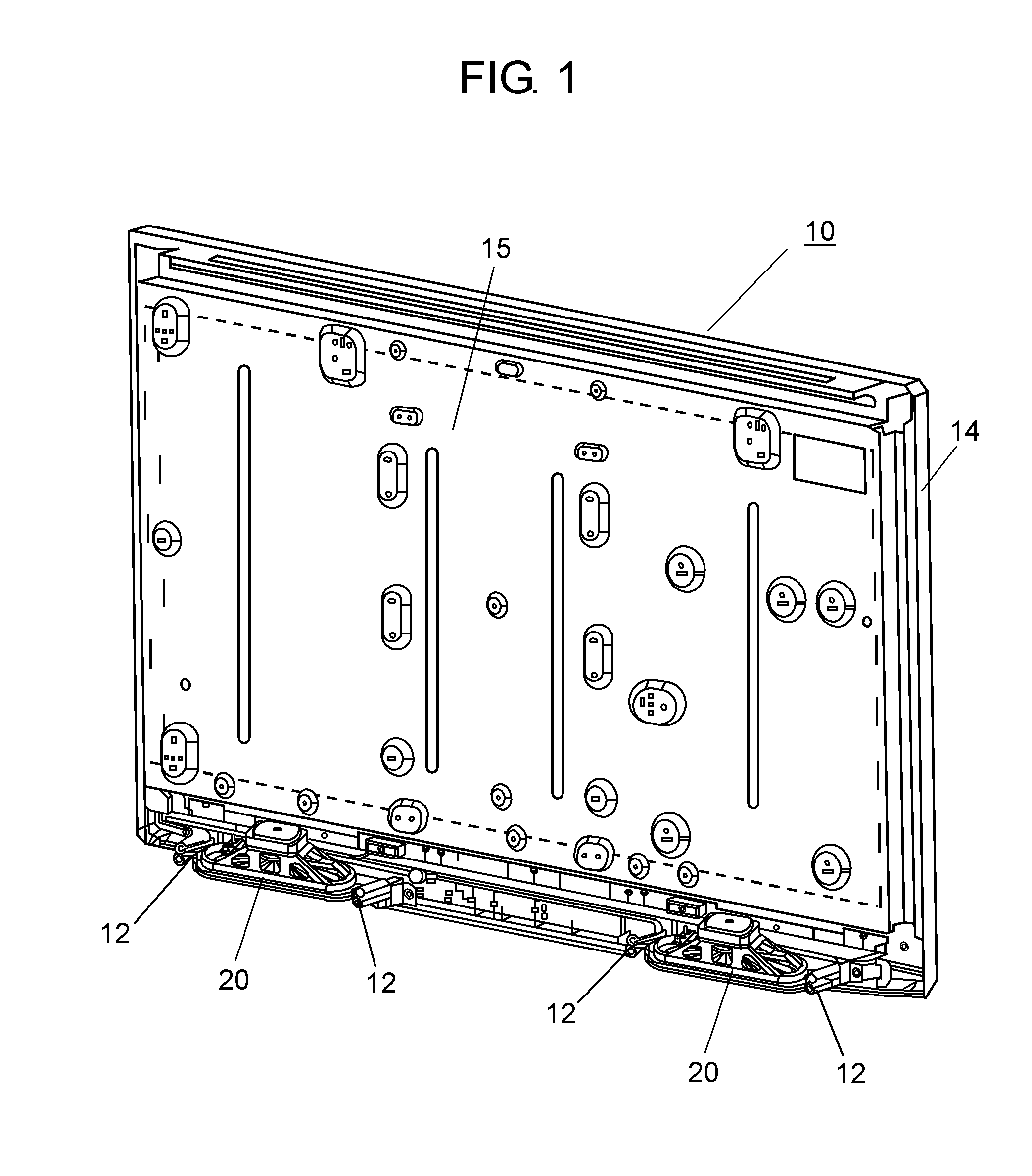
[0026]FIG. 1 illustrates an entire view of television receiver10 having speaker retaining mechanism 12.

[0027]Television receiver 10 is a thin-screen television receiver having a flat panel (e.g., LCD panel). FIG. 1 is a back perspective view of the television receiver 10 when its back cover is removed.

[0028]In television receiver 10, various members are provided in the interior between cabinet 14 and the above-mentioned back cover for sealing the back face of cabinet 14. Cabinet 14 is attached with liquid crystal (LCD) panel 15 for displaying an image. Speaker unit 20 for outputting audio is arranged at the rear face side of cabinet 14 and in the lower part of cabinet 14. Two speaker units 20 function as left and right audio outputs. Each of units 20 is respectively arranged so as to output audio toward the lower side of cabinet 14.

[0029]Speaker un...

second embodiment

[0048]FIG. 9 is an exploded perspective view illustrating the configuration of speaker unit 40 and speaker retaining mechanism 52 for retaining speaker unit 40 in second embodiment of the present invention. FIG. 10 is a perspective view illustrating speaker unit 40 shown in FIG. 9 when viewed from its top.

[0049]Speaker retaining mechanism 52 includes: vibration damping members 42 having a rectangular parallelepiped-like shape (or a cube-like shape) attached to both ends of speaker 21; and speaker bracket 45, as the retaining member, having a hollow space conforming to the shape of vibration damping member 42.

[0050]Speaker unit 40 includes speaker 21 for outputting sound and vibration damping member 42 as described above. Vibration damping members 42 are fixed to both ends of speaker 21 via vibration damping member attachment sections 43. As in the first embodiment, vibration damping member 42 is formed by very soft elastic material having hardness not exceeding 10 degrees for exampl...


PUM


Abstract

A speaker retaining mechanism for retaining a speaker at a predetermined position of a cabinet is disclosed. This speaker retaining mechanism includes: a retaining member that is fixed to the cabinet and that has a hollow space surrounded by an inner wall; and a vibration damping member attached to both ends of the speaker. The vibration damping member is disposed in the hollow space of the retaining member so that the vibration damping member contacts elastically with the inner wall of the retaining member.

Description

[0001]This application is a continuation in part application of Patent Cooperation Treaty Patent Application No. PCT / JP2009 / 282499 (filed on Dec. 13, 2010), which claims priority from Japanese patent application JP 2009-282499 (filed on Dec. 14, 2009).TECHNICAL FIELD[0002]The present invention relates to a speaker retaining mechanism that suppresses a vibration of a speaker from being transmitted to a cabinet and that can provide a higher sound quality by stable attachment and retention of the speaker, and a television receiver including this speaker retaining mechanism.BACKGROUND ART[0003]It is very important to prevent the vibration of a speaker system in a television receiver. Regarding a Cathode Ray Tube (CRT)-type television receiver, a problem has been reported in which the speaker vibration causes the vibration of a shadow mask in the CRT via a cabinet to consequently cause an image having a color shift, for example. Regarding a flat panel television receiver, for example, th...

Claims


Application Information

Patent Timeline
Patent Type & Authority Applications(United States)
IPC IPC(8): H04R1/02
CPCH04R1/2896H04R1/025
Inventor YUKAWA, MASAHIRO
Owner PANASONIC CORP
Why Eureka
Try Eureka