Accelerator pedal apparatus

a pedal apparatus and accelerator technology, applied in the direction of mechanical control devices, instruments, process and machine control, etc., can solve the problems of inability to perform smooth driving, inability to clearly recognize the reaction force feeling of the driver, and difficulty for the driver to recognize the added reaction force, etc., to achieve the effect of reducing fuel consumption

Active Publication Date: 2012-08-30
MIKUNI CORP
View PDF16 Cites 14 Cited by
  • Summary
  • Abstract
  • Description
  • Claims
  • Application Information

AI Technical Summary

Benefits of technology

[0021]According to the above structure, since drive control of the reaction force adding mechanism is appropriately performed based on the various drive information (such as vehicle speed, engine speed, distance against a vehicle in front, road surface information and a drive mode) detected by the drive state detector, it is possible that danger avoidance and danger notification are quickly performed in an appropriate state and that fuel consumption is reduced without providing a feeling of strangeness to a driver.
[0022]According to the accelerator pedal apparatus with the above structure having a hysteresis characteristic on pedaling force, it is possible to quickly perform danger avoidance or danger notification during operation (i.e., depression operation and return operation) of an accelerator pedal and to prevent to provide a feeling of strangeness to a driver when reaction force is added.

Problems solved by technology

Even during return operation of the accelerator pedal, there is a danger of getting too close to a vehicle in front of a driver or that smooth driving cannot be performed when the return amount is insufficient or the return operation is slow.
In this case, there may be a fear that a reaction force feeling cannot be clearly recognized by the driver.
Here, if the reaction force to be added during depression operation is equal to the reaction force to be added during return operation, it is difficult for a driver to recognize the added reaction force.

Method used


Image

  • Accelerator pedal apparatus
  • Accelerator pedal apparatus
  • Accelerator pedal apparatus

Examples


Embodiment Construction

[0031]In the following, embodiments of the present disclosure will be described with reference to the attached drawings.

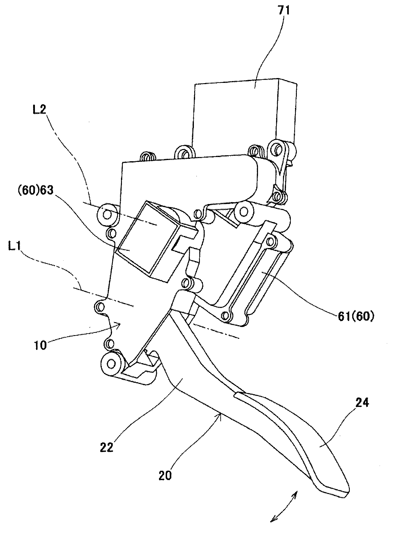
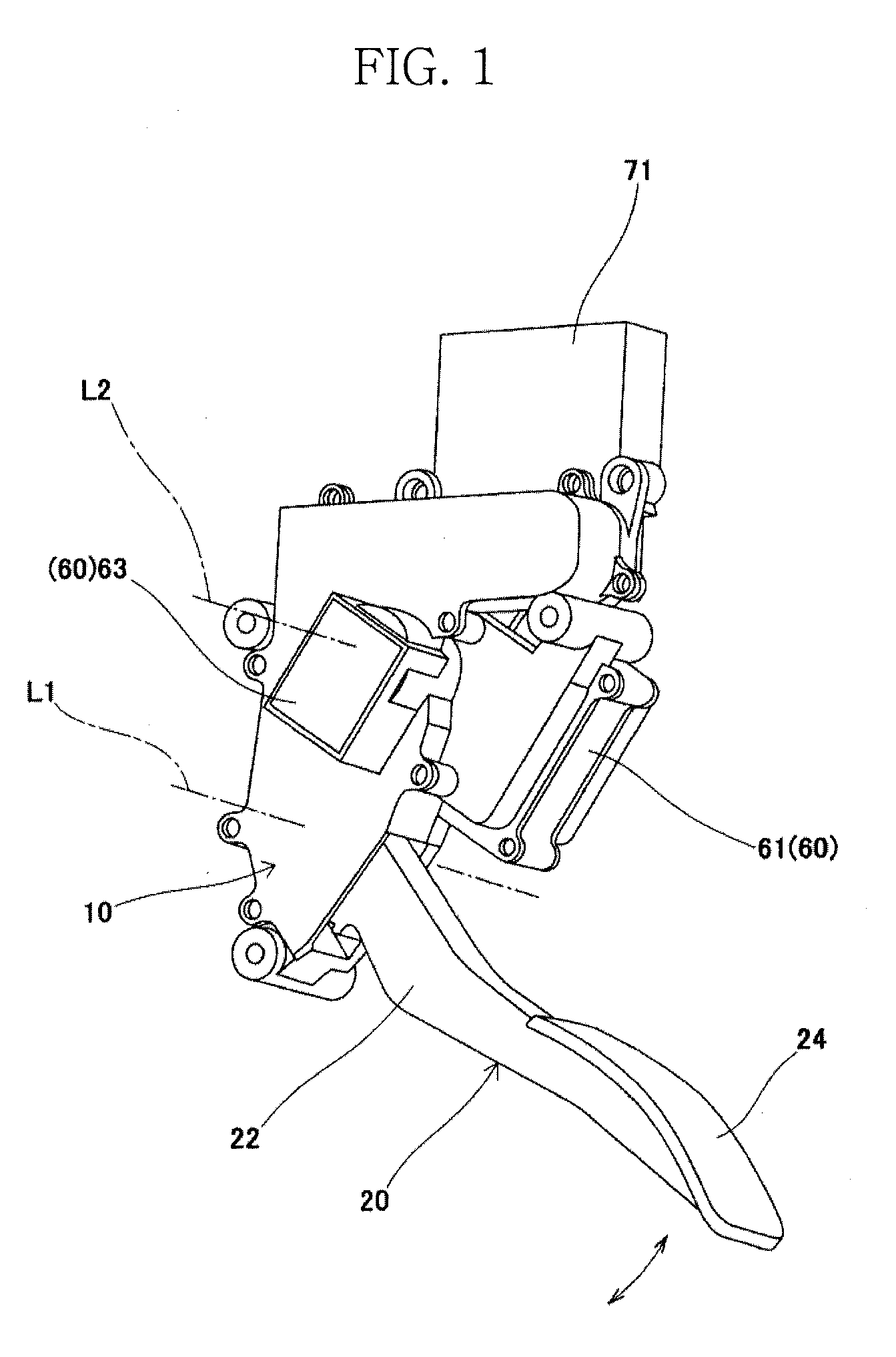
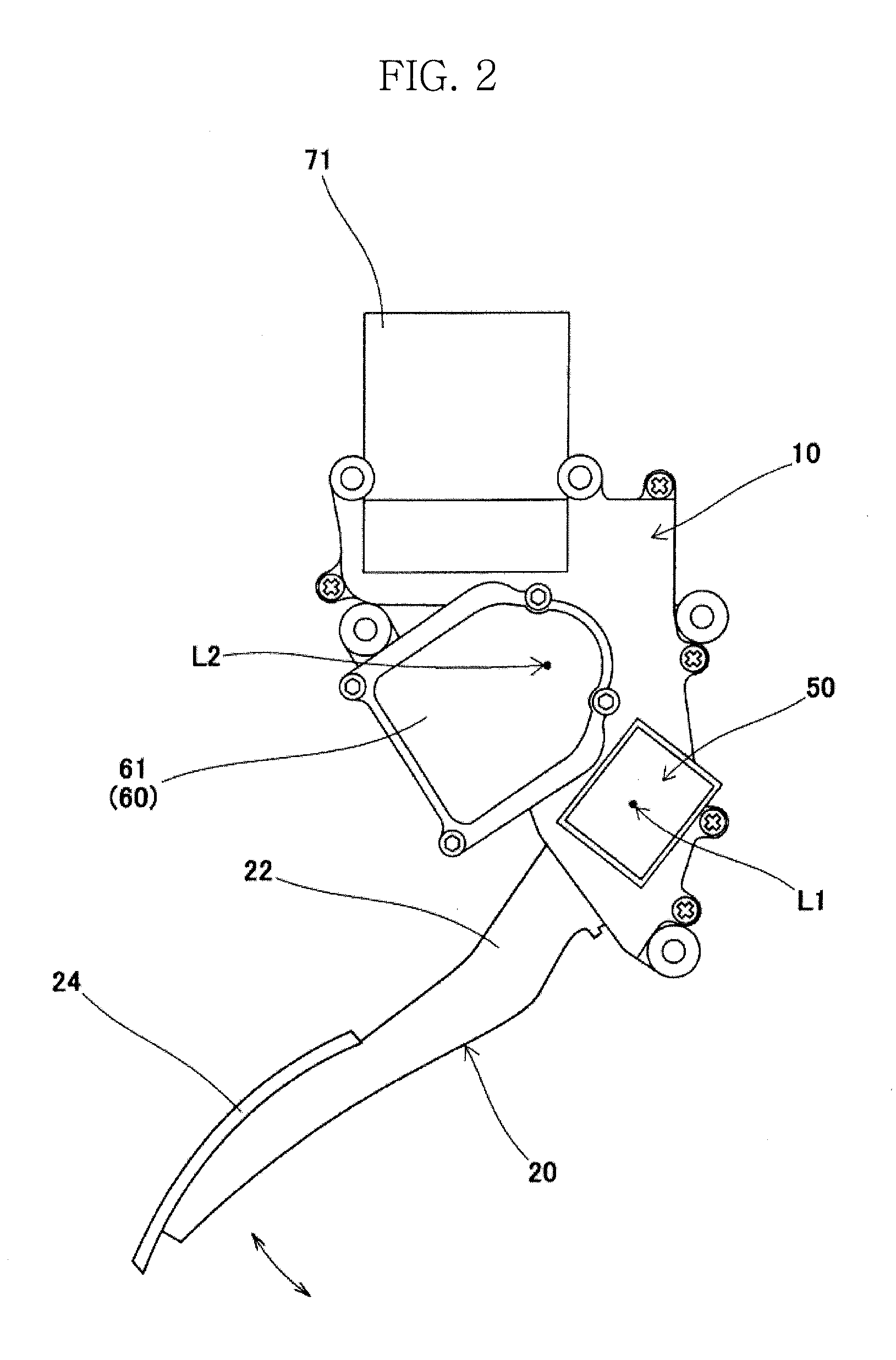
[0032]As illustrated in FIGS. 1 to 4, an accelerator pedal apparatus of an embodiment includes a housing 10 fixed to a vehicle of an automobile and the like, an accelerator pedal 20 supported swingably about a predetermined axis line L1, a return spring 30 which exerts urging force to return the accelerator pedal 20 toward a rest position, a hysteresis generating mechanism 40 which generates hysteresis on pedaling force (i.e., a pedal load) while exerting urging force to return the accelerator pedal 20 toward the rest position, an accelerator position sensor (APS) 50 as an operation detector to detect a rotational angle position and a rotational direction of the accelerator pedal 20, a reaction force adding mechanism 60 which generates reaction force to return the accelerator pedal 20 toward the rest position under predetermined conditions, a control system 70 as c...


PUM


Abstract

An accelerator pedal apparatus includes an accelerator pedal, a hysteresis generating mechanism which generates hysteresis on pedaling force, a reaction force adding mechanism which adds reaction force to push back the accelerator pedal toward a rest position, and controller which performs drive control of the reaction force adding mechanism, while the controller performs drive control of the reaction force adding mechanism so that reaction force is added during returning as well as during depressing of the accelerator pedal under predetermined conditions as the reaction force being larger than pedaling force difference between pedaling force at the depression side and pedaling force at the return side of the pedaling force hysteresis to obtain an appropriate accelerator feeling and to quickly perform danger avoidance or danger notification.

Description

CROSS-REFERENCE TO RELATED APPLICATIONS[0001]This application claims the priority benefit of Japanese Patent Application No. 2011-036863, filed Feb. 23, 2011, in the Japanese Patent Office, the disclosure of which is incorporated herein by reference.BACKGROUND[0002]1. Field[0003]The present disclosure relates to an accelerator pedal apparatus applied to vehicles and the like having a drive-by-wire system, and in particular, relates to an accelerator pedal apparatus including a reaction force generating mechanism which generates reaction force (i.e. push-back force) against pedaling force of a pedal arm for danger avoidance, danger notification or the like.[0004]2. Description of the Related Art[0005]For an engine mounted on an automobile and the like, an accelerator pedal apparatus including a hysteresis generating mechanism to provide a hysteresis characteristic to relation between a stroke (i.e., a depression amount) and pedaling force of an accelerator pedal as pedaling force dur...

Claims


Application Information

Patent Timeline
Patent Type & Authority Applications(United States)
IPC IPC(8): B60Q9/00G05G1/44
CPCB60K26/021B60K2026/023G05G1/44B60W10/18B60T7/22B60T8/172G05G5/03
Inventor YAMAZAKI, SHIGERUKASHIYAMA, MEGURUKUMAMOTO, MASATOOOSAWA, TSUYOSHITOUHACHI, HIROMUTSU
Owner MIKUNI CORP
Why Eureka
Try Eureka