Device And Method For Cutting Through The Adhesive Bead Of Panes That Have Been Fixed By Bonding

a technology of adhesive beads and cutting devices, which is applied in the direction of chainsaws, gang saw mills, sawing apparatus, etc., can solve the problems of large tensile load on the separating means, different winding devices to be provided, and high cost of rearrangement after cutting through the adhesive beads. , to achieve the effect of time-saving operation and easy adaptation

Inactive Publication Date: 2012-09-06
C & E FEIN
View PDF6 Cites 10 Cited by
  • Summary
  • Abstract
  • Description
  • Claims
  • Application Information

AI Technical Summary

Benefits of technology

[0011]It is a forth object of the invention to disclose a device for cutting through the adhesive bead of panes that can be easily adapted to different geometric conditions.
[0012]It is a fifth object of the invention to disclose a device for cutting through the adhesive bead of panes that allows for a time-saving operation even when handled by only one person.

Problems solved by technology

A disadvantage of the known device and of the known method is that different winding devices have to be provided for winding-on the cutting wire in the one and in the other direction.
In addition, the rearrangement after cutting through the one half of the adhesive bead is expensive.
A disadvantage of the known device and of the known method is that the angle between the separating means and the adhesive bead for a large part of the adhesive bead to be cut through is clearly greater than 90°, which leads to a large amount of tensile loading on the separating means and brings about either a non-clean cut or in the case of extreme tensile loading can even lead to the separating means tearing.

Method used


Image

  • Device And Method For Cutting Through The Adhesive Bead Of Panes That Have Been Fixed By Bonding
  • Device And Method For Cutting Through The Adhesive Bead Of Panes That Have Been Fixed By Bonding
  • Device And Method For Cutting Through The Adhesive Bead Of Panes That Have Been Fixed By Bonding

Examples


Embodiment Construction

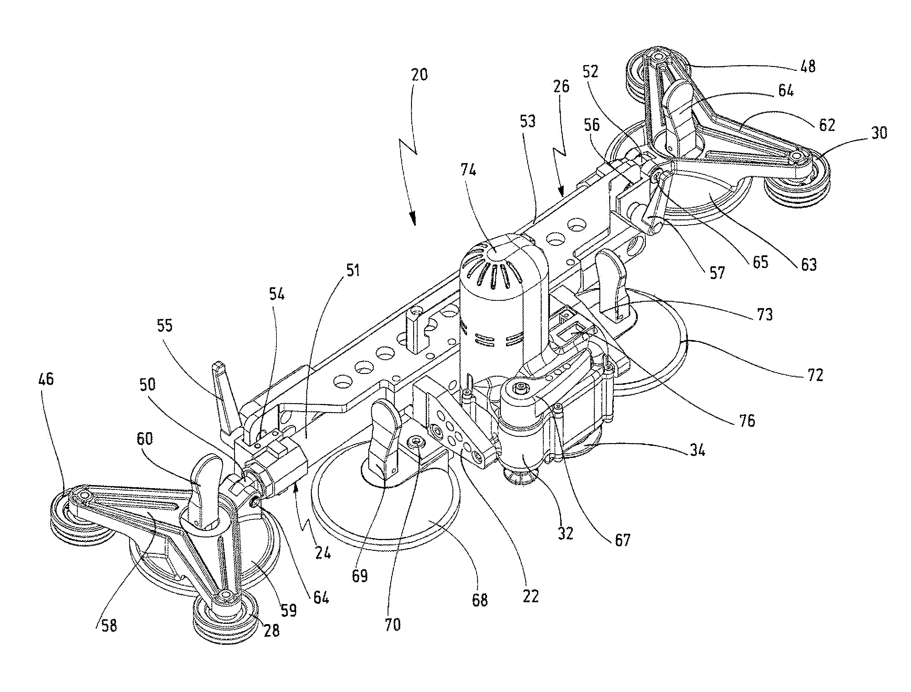
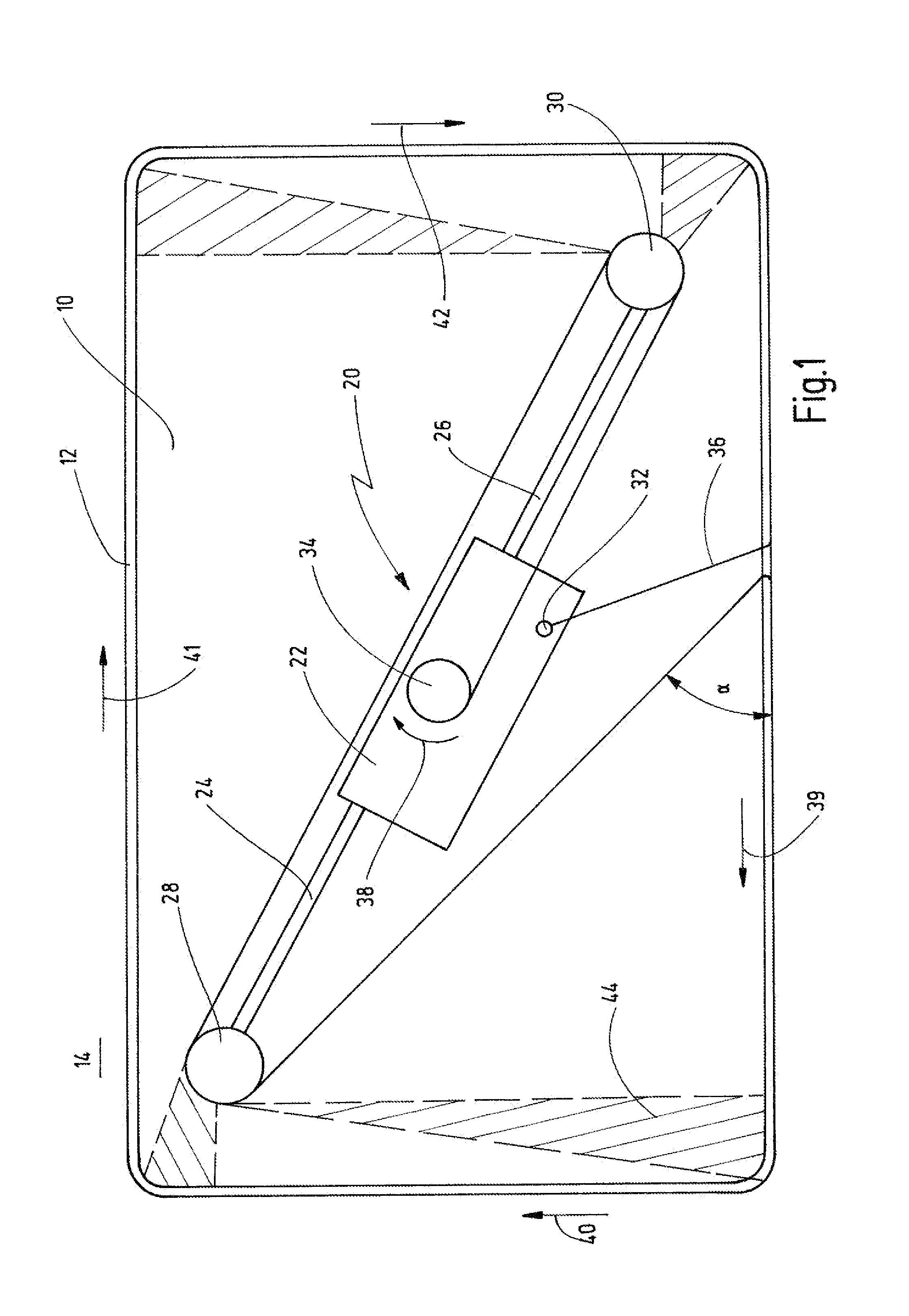
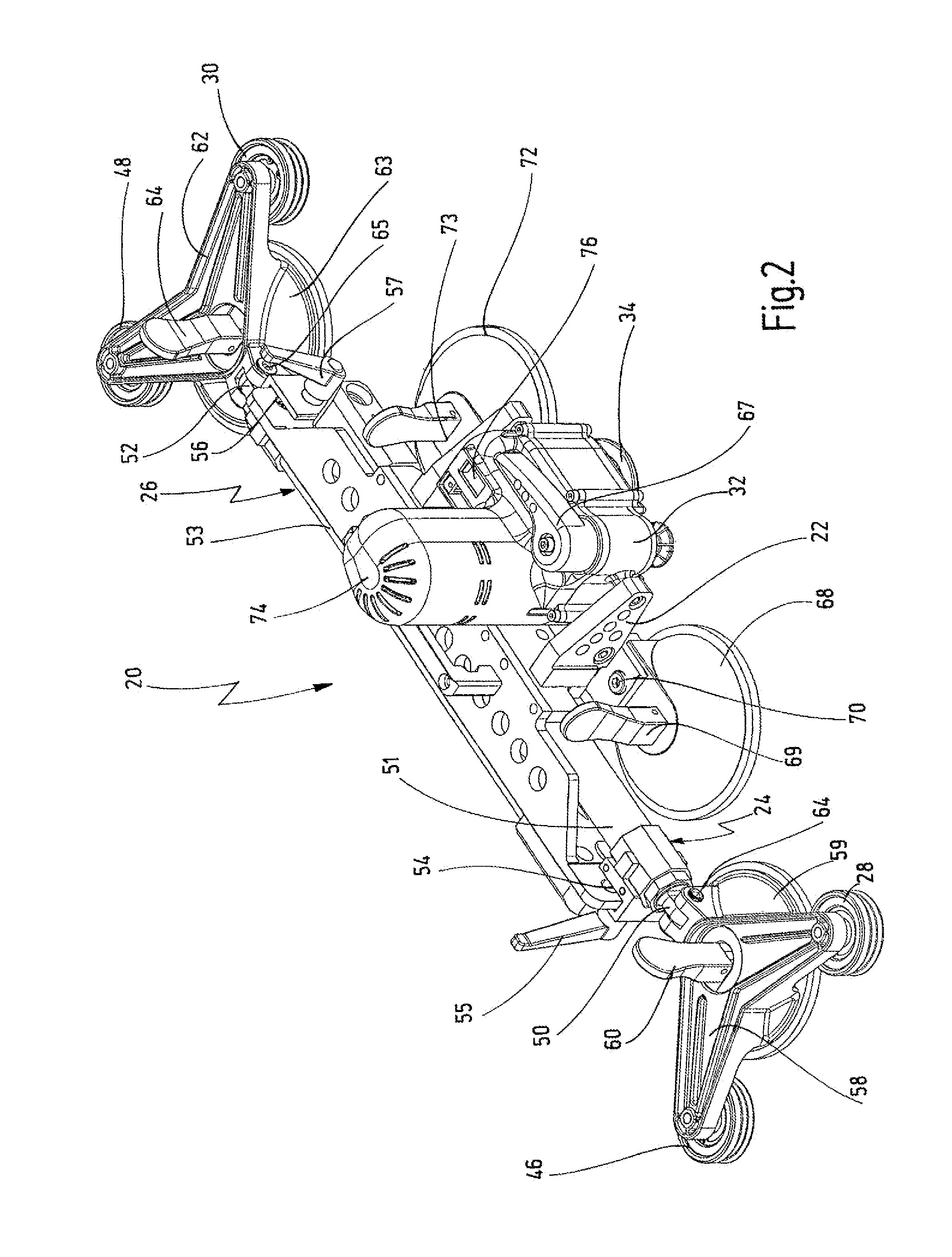
[0060]The principle method of operation of the device according to the invention may be explained initially by way of FIG. 1.

[0061]FIG. 1 shows a pane 10 in the view from the outside, said pane has been fixed from the outside by bonding onto a vehicle body flange 14 by means of a circumferential bead 12. The adhesive bead 12 is a very tough material, for instance based on polyurethane. There is only a very narrow gap between the adhesive bead 12 and the circumferential vehicle body flange 14. If a pane 10 of this type has to be replaced, for instance as a result of a stone damaging the windscreen, the adhesive bead 12 has to be cut through completely, it being important, in particular, not to damage the circumferential vehicle body flange 14, so that once a new pane has been fixed by bonding again there are no disadvantageous influences to be feared, for instance caused by rust.

[0062]According to the invention, the cutting through of the adhesive bead 12 is effected with the aid of ...


PUM

PropertyMeasurementUnit
cutting angleaaaaaaaaaa
removal angleaaaaaaaaaa
angleaaaaaaaaaa

Abstract

A device and a method for cutting through the adhesive bead of panes that have been fixed by bonding is specified, said device having a base body on which at least one suction plate for fixing on a pane to be separated out as well as one motor-drivable coil for winding-on a separating wire are accommodated, wherein at least two guide rollers are held on the base body by means of extension arms at a distance which is adjustable in respect to each other. The device is preferably positioned approximately diagonally on the pane in such a manner that the guide rollers are situated on the outer ends of the extension arms in the vicinity of the corner regions of the pane.

Description

CROSS REFERENCES TO RELATED APPLICATIONS [0001]This application claims priority from German patent application 102011013790.4, filed on Mar. 3, 2011. The entire contents of this priority application is incorporated herein by reference.BACKGROUND OF THE INVENTION [0002]The invention relates to a device for cutting through the adhesive bead of panes that have been fixed by bonding, said device having a base body on which at least one suction plate for fixing on a pane to be removed as well as one motor-drivable coil for winding-on a separating means are accommodated.[0003]The invention also relates to a method for cutting through the adhesive bead of panes that have been fixed by bonding, where a separating means is guided around the adhesive bead of the pane from the outside, the adhesive bead is pierced from the outside with at least one end of the separating means, a device, having a base body on which a motor-drivable coil for winding-on the separating means is accommodated, is fa...

Claims


Application Information

Patent Timeline
Patent Type & Authority Applications(United States)
IPC IPC(8): B26D1/547B26D3/00B26D7/26
CPCB60J10/0088B26D1/547Y10T83/04Y10T83/68Y10T83/9292Y10T156/1052Y10T156/12
Inventor SEEBAUER, RALF
Owner C & E FEIN
Why Eureka
Try Eureka