Evaporative emission control device for internal combustion engine

Inactive Publication Date: 2012-09-06
MITSUBISHI MOTORS CORP
View PDF38 Cites 24 Cited by
  • Summary
  • Abstract
  • Description
  • Claims
  • Application Information

AI Technical Summary

Benefits of technology

[0012]When the internal pressure of the fuel tank detected by the pressure detector becomes higher than or equal to the predetermined value, the canister opening-and-closing unit is switched to shut off the caniste

Problems solved by technology

If the fuel tank is kept hermetically shut off by the fuel tank shutoff valve, however, the pressure in the fuel tank occasionally increases to high pressure as the fuel in the fuel tank

Method used


Image

  • Evaporative emission control device for internal combustion engine
  • Evaporative emission control device for internal combustion engine
  • Evaporative emission control device for internal combustion engine

Examples


first embodiment

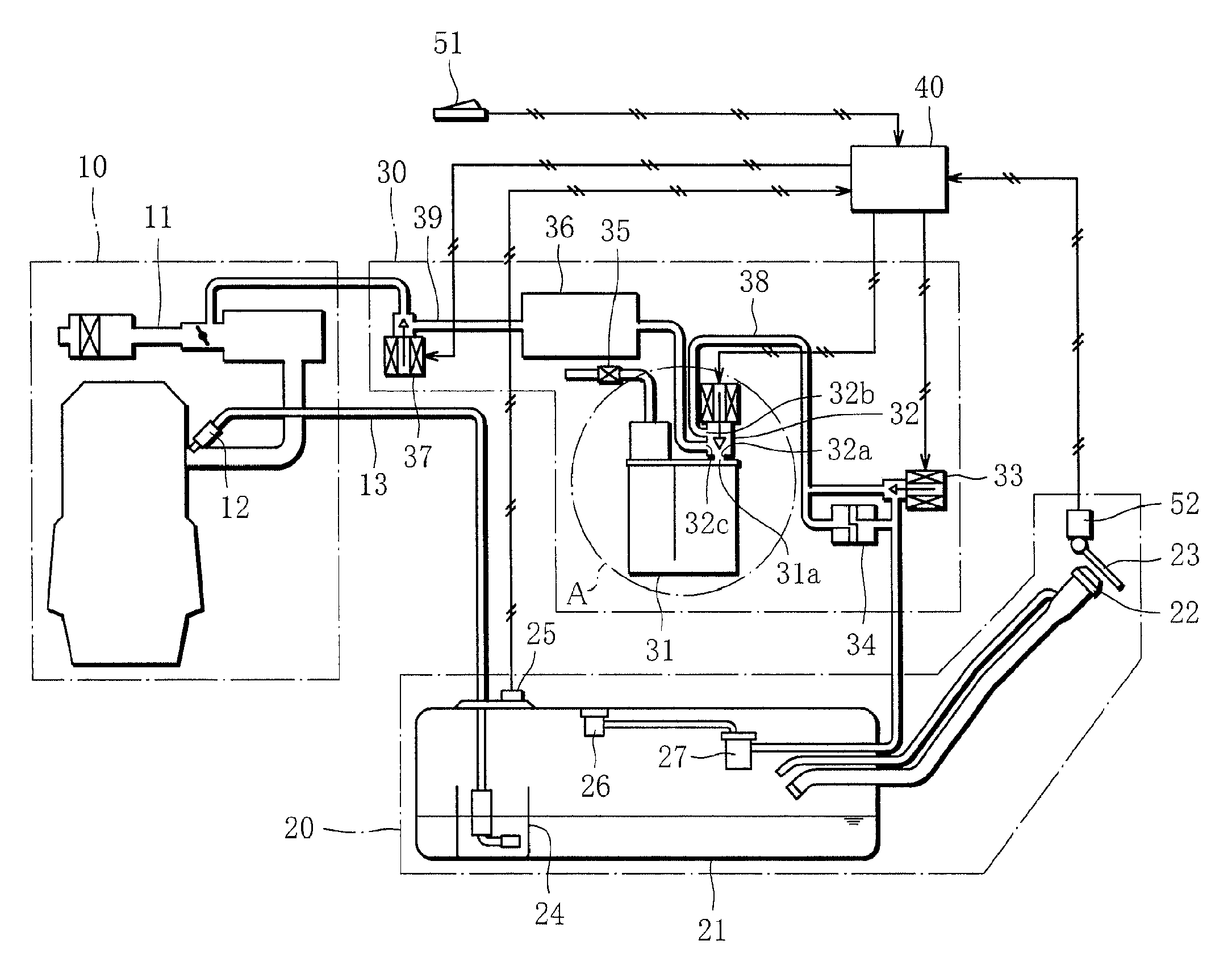
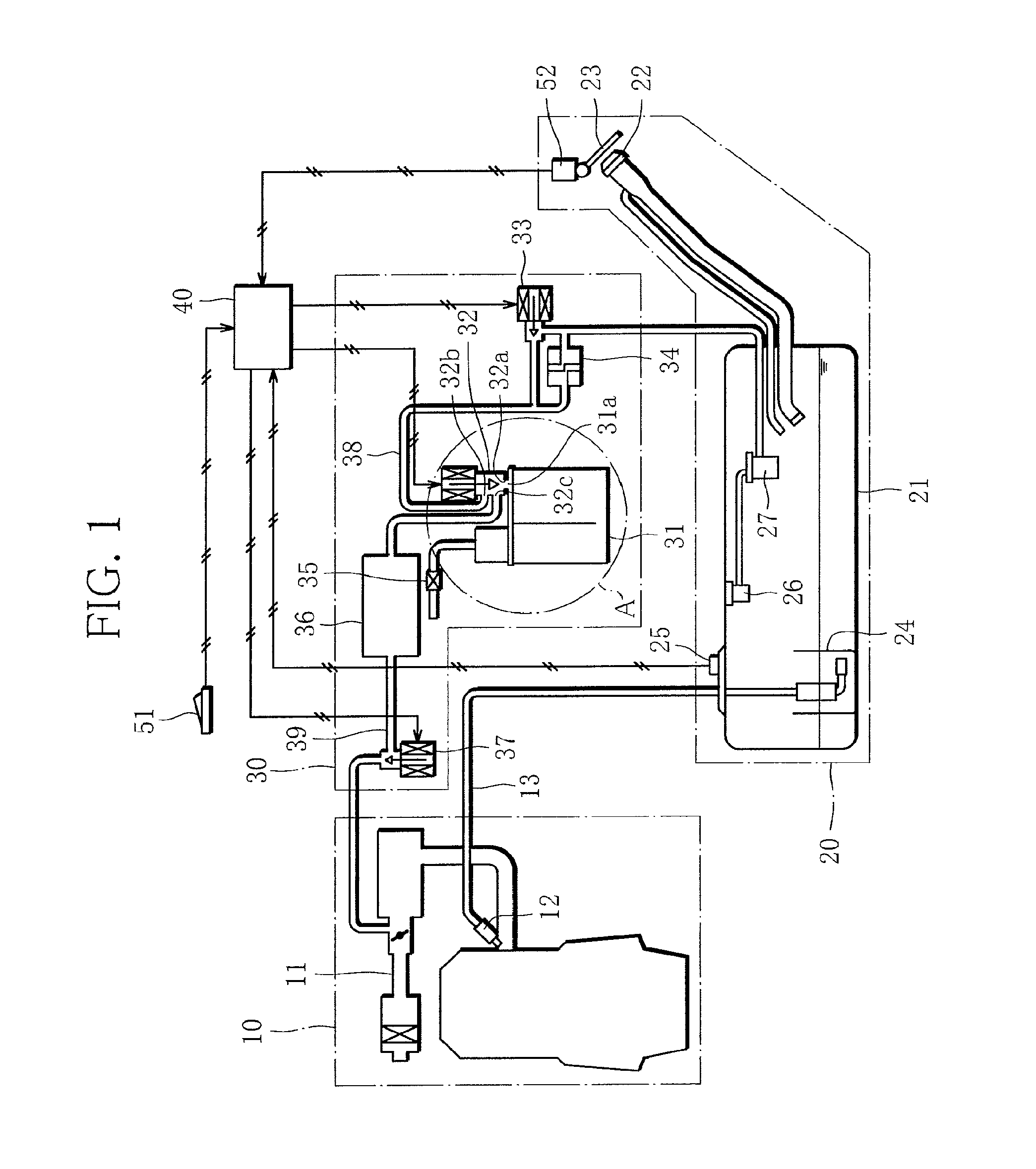
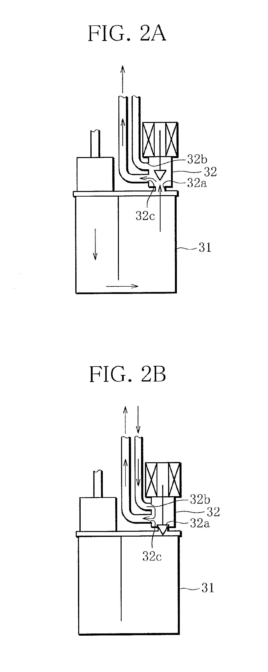
[0023]FIG. 1 schematically illustrates the configuration of a evaporative emission control device for an internal combustion chamber according to a first embodiment of the present invention. FIG. 2A is an enlarged view of a part A in FIG. 1 and illustrates an unoperated state of a canister shutoff valve 32, FIG. 2B is an enlarged view of the part A in FIG. 1 and illustrates an operated state of the canister shutoff valve 32, and in the figures, arrows indicate flowing directions of a fuel evaporative gas. In the following, the configuration of the evaporative emission control device for an internal combustion engine will be described.

[0024]As illustrated in FIGS. 1, 2A and 2B, the evaporative emission control device according to the first embodiment of the present invention generally comprises an engine (internal combustion engine) 10 mounted on a motor vehicle, a fuel storage section 20 for storing fuel, a fuel evaporative gas treatment section 30 for treating a fuel evaporative ga...

second embodiment

[0051]A evaporative emission control device for an internal combustion engine according to a second embodiment of the present invention will be now described.

[0052]The second embodiment differs from the first embodiment in the method of controlling the internal pressure of the fuel tank 21 by the ECU 40. Thus, in the following, the manner of how the internal pressure of the fuel tank 21 is controlled by the ECU 40 will be explained.

[0053]FIG. 4 illustrates the operation of the purge control valve 37, the fuel tank shutoff valve 33 and the canister shutoff valve 32 of the evaporative emission control device according to the second embodiment of the present invention, together with change with time of the internal pressure of the fuel tank.

[0054]As illustrated in FIG. 4, when the pressure in the fuel tank 21 is “0” during operation of the engine 10, the drive signal is supplied to the canister shutoff valve 32 to energize and thereby close the canister shutoff valve 32 (at time (i) in...

third embodiment

[0062]A evaporative emission control device for an internal combustion engine according to a third embodiment of the present invention will be now described.

[0063]The third embodiment differs from the first embodiment in that a canister shutoff valve 32′ is used instead. In the following, the configuration of the fuel evaporative emission control device according to the third embodiment will be explained.

[0064]FIG. 5 schematically illustrates the configuration of the evaporative emission control device according to the third embodiment of the present invention. FIG. 6A is an enlarged view of a part A in FIG. 5 and illustrates an unoperated state of the canister shutoff valve 32′, FIG. 6B is an enlarged view of the part A in FIG. 5 and illustrates an operated state of the canister shutoff valve 32′, and in the figures, arrows indicate flowing directions of the fuel evaporative gas. In the following, the configuration of the evaporative emission control device for an internal combusti...


PUM


Abstract

A canister shutoff valve has a canister connection port for communicating with a canister, a vapor line connection port connected to a vapor line, and a purge line connection port connected to a purge line. When the canister shutoff valve is de-energized and thus is open, the canister connection port, the vapor line connection port and the purge line connection port communicate with one another, allowing fuel evaporative gas to flow into and out of the canister. When the canister shutoff valve is energized and thus is closed, the canister connection port is blocked and only the vapor line connection port and the purge line connection port communicate with each other, thereby preventing the fuel evaporative gas from flowing into and out of the canister.

Description

BACKGROUND OF THE INVENTION[0001]1. Field of the Invention[0002]The present invention relates to a evaporative emission control device for an internal combustion engine, and more particularly, to adsorption control in conjunction with a canister that adsorbs a fuel evaporative gas produced in a hermetic fuel tank.[0003]2. Description of the Related Art[0004]Techniques for preventing a fuel evaporative gas produced within a fuel tank from being discharged to the atmosphere have conventionally been known, wherein a canister is provided for communication with the fuel tank, and a fuel tank shutoff valve is inserted in a passage communicating the fuel tank and the canister with each other. The fuel tank shutoff valve is controlled so as to hermetically shut off the fuel tank at times other than refueling, and to open during refueling to allow the fuel evaporative gas to flow toward the canister so that the fuel evaporative gas may be adsorbed by the canister.[0005]If the fuel tank is ke...

Claims


Application Information

Patent Timeline
IPC IPC(8): F02M33/02
CPCF02M25/089F02M25/0836
Inventor SANO, TAKAYUKIOHIZUMI, HIROSHIARAKI, KOYUKOJIMA, YASUOOHHASHI, TOMOHIROOMI, YOSHIHIRO
Owner MITSUBISHI MOTORS CORP
Why Eureka
Try Eureka