Wireless power feeder, wireless power receiver, and wireless power transmission system, and coil

Active Publication Date: 2012-09-06
TDK CORPARATION
View PDF1 Cites 20 Cited by
  • Summary
  • Abstract
  • Description
  • Claims
  • Application Information

AI Technical Summary

Benefits of technology

[0031]According to the present invention, control of the magnitude of feeding power or power feeding directio

Problems solved by technology

The type (B) utilizing radio wave is available in

Method used


Image

  • Wireless power feeder, wireless power receiver, and wireless power transmission system, and coil
  • Wireless power feeder, wireless power receiver, and wireless power transmission system, and coil
  • Wireless power feeder, wireless power receiver, and wireless power transmission system, and coil

Examples


Example

First Embodiment

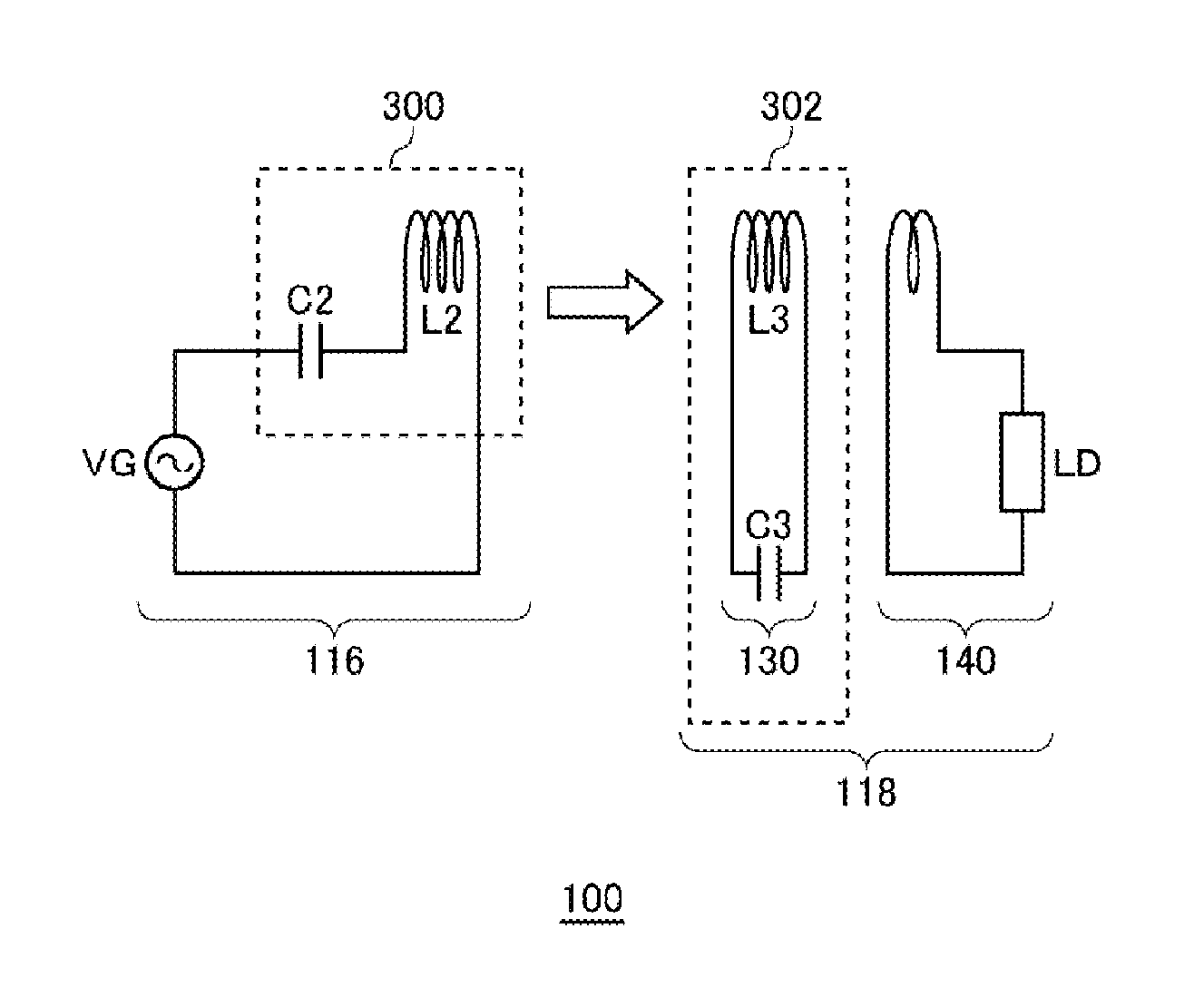
[0080]FIG. 3 is a view schematically illustrating a wireless power transmission system according to a first embodiment. A power transmission control circuit 200 functions as an AC power supply and supplies AC power of a drive frequency fo to the feeding coil L2. The power transmission control circuit 200 in the first embodiment functions merely as a power feeding source VG (FIG. 1). The drive frequency fo may be a fixed frequency. For example, the drive frequency fo may be set to the resonance frequency fr1. As a matter of course, the power transmission control circuit 200 may be configured to be able to change the drive frequency fo.

[0081]The wireless power receiver 118 includes a receiving coil circuit 130 and a loading circuit 140. In the receiving coil circuit 130, a power receiving LC resonance circuit 302 (refer to FIG. 1) is formed by a receiving coil L3 and capacitor C3. When the feeding coil L2 generates an AC magnetic field at the resonance frequency fr1, t...

Example

Second Embodiment

[0102]FIG. 13 is a view schematically illustrating the wireless power transmission system according to a second embodiment. In the second embodiment, not the power receiving control circuit 202 but a power transmission control circuit 200 rotates the non-uniform type feeding coil L2 so as to control feeding power. The power feeding side magnetic body F2 is installed inside the feeding coil L2. The power receiving side magnetic body F3 is not installed inside the receiving coil L3. Thus, the magnetic characteristics of the feeding coil L2 in the circumferential direction thereof are non-uniform; while the magnetic characteristics of the receiving coil L3 in the circumferential direction thereof are uniform.

[0103]The power transmission control circuit 200 functions as an AC power supply and supplies AC power of a drive frequency fo to the feeding coil L2. The power transmission control circuit 200 in the second embodiment functions not only as a power feeding source V...

Example

Third Embodiment

[0116]FIG. 22 is a view schematically illustrating the wireless power transmission system 100 according to the third embodiment. A power repeater 210 is added to the wireless power transmission system 100 of the third embodiment. The power receiving side magnetic body F3 is installed inside the receiving coil L3. Other configurations are the same as those of the second embodiment.

[0117]The power repeater 210 is an LC resonance circuit having the same resonance characteristics as the receiving coil L3 and includes a repeating coil L5 and a capacitor C5. A repeating side magnetic body F5 is installed in the repeating coil L5 in the same manner as the power feeding side magnetic body F2 and the power receiving side magnetic body F3. AC power fed from the wireless power feeder 116 is once received by the repeating coil L5. That is, the power repeater 210 has a function of transferring the AC power fed from the feeding coil L2 of the wireless power feeder 116 to the recei...


PUM


Abstract

A wireless power feeder feeds power from a feeding coil to a receiving coil by wireless using a magnetic field resonance phenomenon. The feeding coil is constructed in a rotatable manner. A power transmission control circuit that supplies AC power to the feeding coil so as to make the feeding coil feed the AC power to the receiving coil. The feeding coil is constructed such that the magnetic characteristics thereof in the circumferential direction are made non-uniform. Concretely, a magnetic body is installed at only a part of the circumference of the feeding coil to make the magnetic characteristics of the feeding coil in the circumferential direction non-uniform.

Description

BACKGROUND OF THE INVENTION[0001]1. Field of the Invention[0002]The present invention relates to wireless power feeding and, more particularly, to a power control thereof.[0003]2. Description of Related Art[0004]A wireless power feeding technique of feeding power without a power cord is now attracting attention. The current wireless power feeding technique is roughly divided into three: (A) type utilizing electromagnetic induction (for short range); (B) type utilizing radio wave (for long range); and (C) type utilizing resonance phenomenon of magnetic field (for intermediate range).[0005]The type (A) utilizing electromagnetic induction has generally been employed in familiar home appliances such as an electric shaver; however, it can be effective only in a short range. The type (B) utilizing radio wave is available in a long range; however, it has small electric power. The type (C) utilizing resonance phenomenon is a comparatively new technique and is of particular interest because ...

Claims


Application Information

Patent Timeline
IPC IPC(8): H02J17/00
CPCH01F38/14H02J5/005H02J50/90H02J50/50H02J50/12
Inventor GOTANI, AKIRA
Owner TDK CORPARATION
Why Eureka
Try Eureka