Vibrator element, vibrator, oscillator, and electronic apparatus
a vibrating element and oscillator technology, applied in the direction of oscillator, piezoelectric/electrostrictive/magnetostrictive device details, piezoelectric/electrostrictive/electrostrictive device details, etc., can solve the problem of lowering the frequency due to the formation of the weight section at the tip portion, unstable vibration and deformation of the vibrational frequency of the vibrating arm section. , to achieve the effect o
- Summary
- Abstract
- Description
- Claims
- Application Information
AI Technical Summary
Benefits of technology
Problems solved by technology
Method used
Image
Examples
first embodiment
[0029]A first embodiment of the invention will hereinafter be explained with reference to FIGS. 1A through 1C.
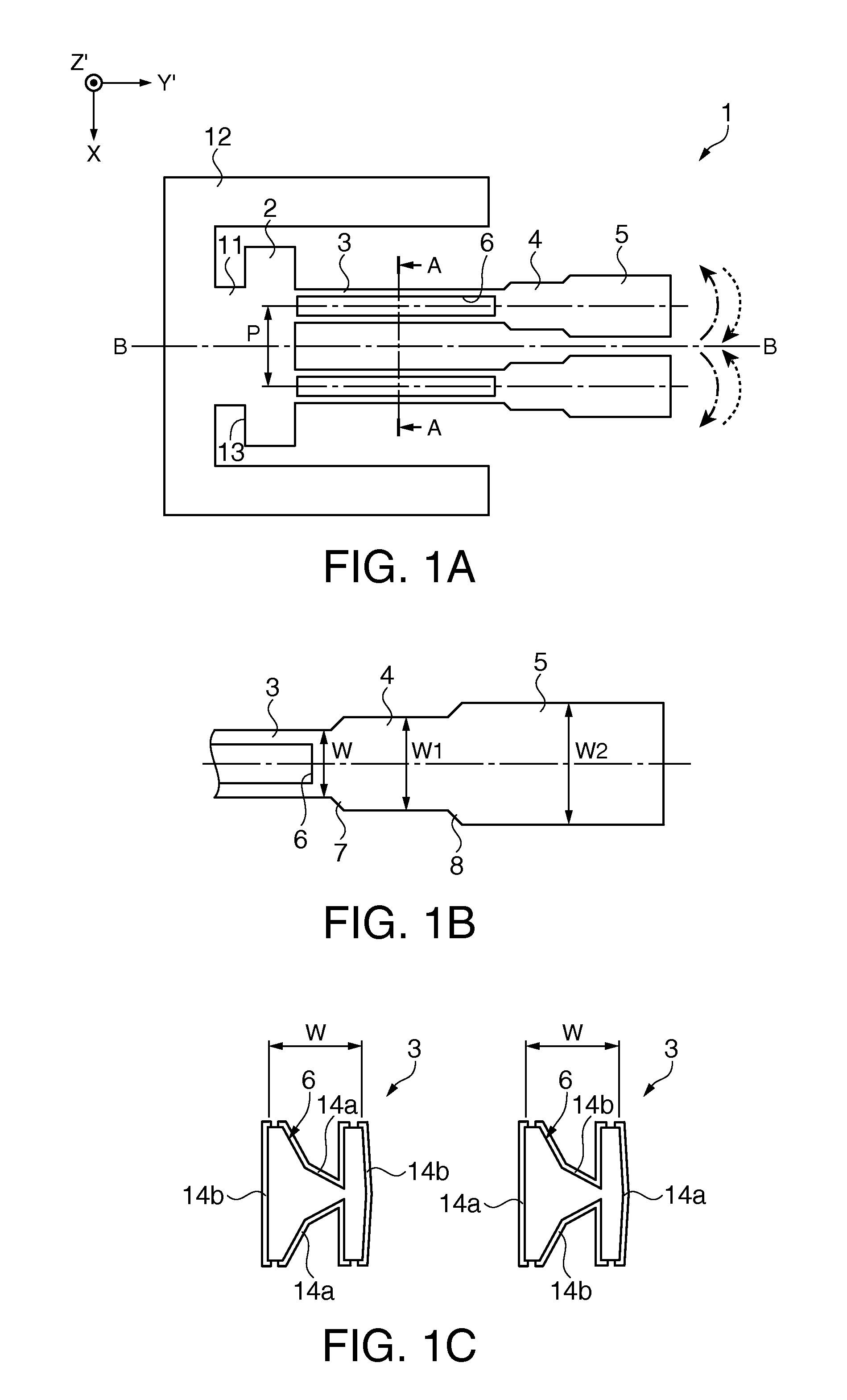
[0030]FIG. 1A is a schematic plan view showing the quartz crystal vibrator element according to the first embodiment. FIG. 1B is a partial enlarged view of the quartz crystal vibrator element shown in FIG. 1A. FIG. 1C is a cross-sectional view along the line A-A shown in FIG. 1A.
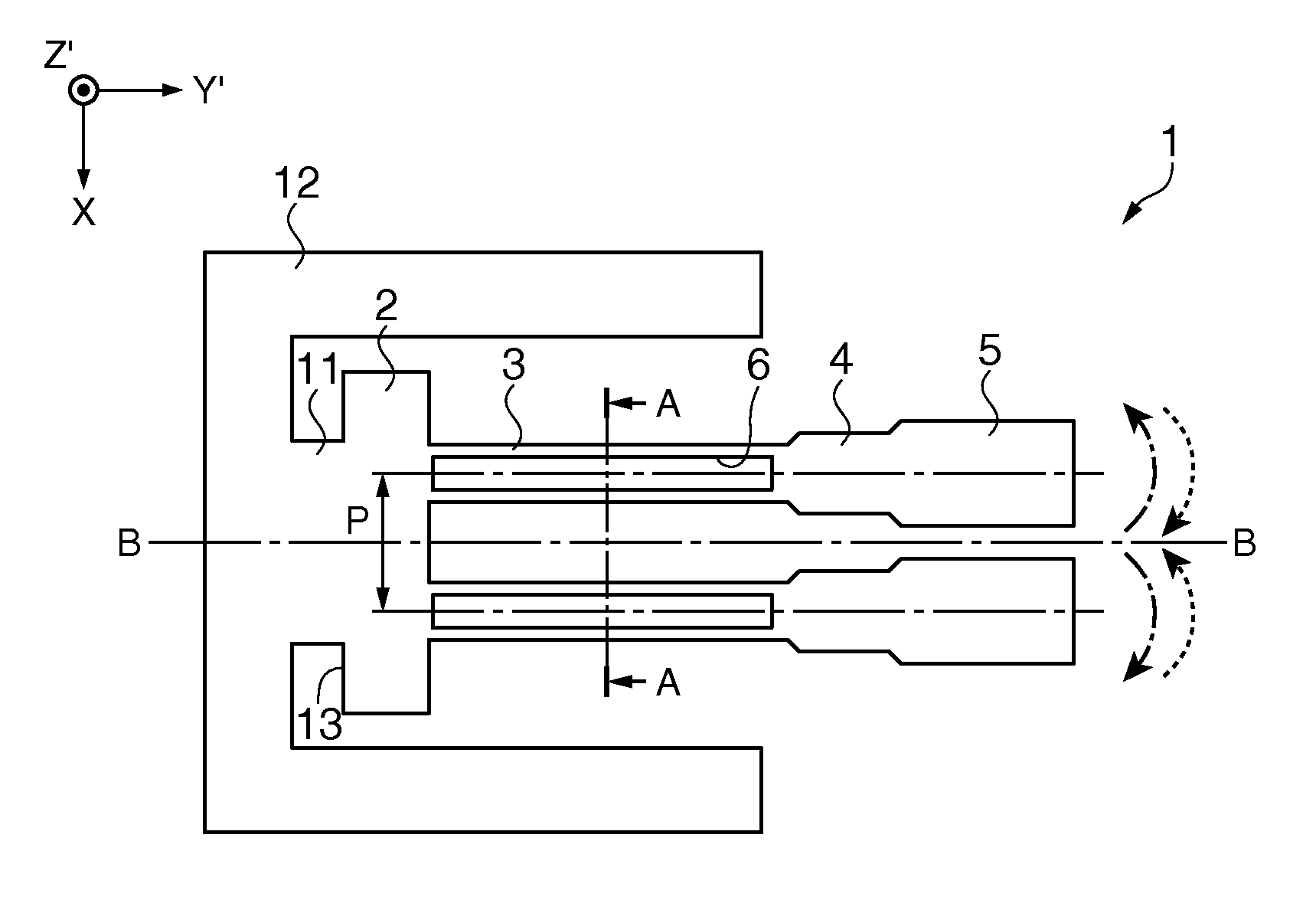
[0031]As shown in FIG. 1A, the quartz crystal vibrator element 1 as the vibrator element is provided with the base portion 2, two vibrating arm sections 3, two intermediate weight sections 4, two tip weight sections 5, elongated groove sections 6, a coupling section 11, and a support section 12. The quartz crystal vibrator element 1 has a Z-axis as an optical axis of the quartz crystal column, an X-axis as an electrical axis perpendicular to the Z-axis, and a Y-axis as a mechanical axis perpendicular to the x-axis, and is cut out from a Z-cut quartz crystal plate along a plane obtained by tilting the...
first modified example
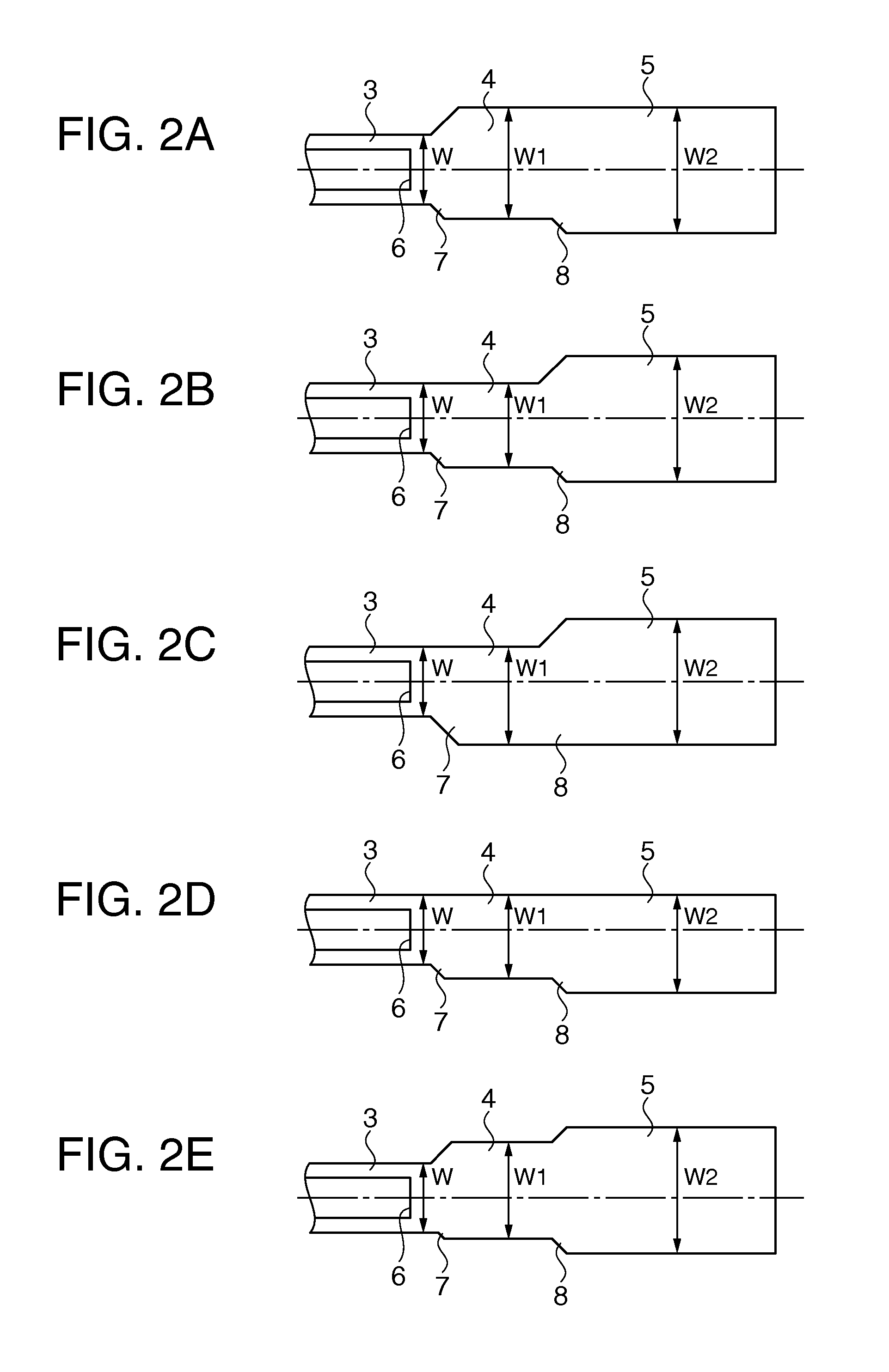
[0044]FIG. 2A shows a first modified example. As shown in FIG. 2A, the intermediate weight section 4 of the first modified example is not formed axisymmetrically about the dashed dotted line, while the tip weight section 5 is formed axisymmetrically about the dashed dotted line. Further, one end of the intermediate weight section 4 defining the arm width W1 and one end of the tip weight section 5 defining the arm width W2 are formed on the same straight line.
[0045]Further, in the first modified example, although it is assumed that the intermediate weight section 4 is not formed axisymmetrically about the dashed dotted line, the configuration is not limited thereto, but it is also possible to assume that the intermediate weight section 4 is formed axisymmetrically about the dashed dotted line, while the tip weight section 5 is not formed axisymmetrically about the dashed dotted line.
second modified example
[0046]FIG. 2B shows a second modified example. As shown in FIG. 2B, the intermediate weight section 4 of the second modified example is not formed axisymmetrically about the dashed dotted line, while the tip weight section 5 is formed axisymmetrically about the dashed dotted line similarly to the case of the first modified example.
[0047]Further, the difference from the modified example 1 is the point that one end of the intermediate weight section 4 defining the arm width W1 and one end of the vibrating arm section 3 defining the arm width W are formed on the same straight line.
[0048]Further, in the second modified example, although it is assumed that the one end of the intermediate weight section 4 defining the arm width W1 is formed on the same straight line with the one end of the vibrating arm section 3 defining the arm width W, the configuration is not limited thereto, but it is also possible to assume that the one end of the intermediate weight section 4 defining the arm width...
PUM
 Abstract
Description
Claims
Application Information
 - R&D
- Intellectual Property
- Life Sciences
- Materials
- Tech Scout
- Unparalleled Data Quality
- Higher Quality Content
- 60% Fewer Hallucinations
Browse by: Latest US Patents, China's latest patents, Technical Efficacy Thesaurus, Application Domain, Technology Topic, Popular Technical Reports.
© 2025 PatSnap. All rights reserved.Legal|Privacy policy|Modern Slavery Act Transparency Statement|Sitemap|About US| Contact US: help@patsnap.com


