Support member

Active Publication Date: 2012-09-06
TEIKOKU PISTON RING CO LTD +1
View PDF6 Cites 4 Cited by
  • Summary
  • Abstract
  • Description
  • Claims
  • Application Information

AI Technical Summary

Benefits of technology

[0020]According to the support member of the present invention, the contact with the member to which the support member is attached is improved and the member i

Problems solved by technology

However, with the wear-preventing sleeve shown in Japanese Patent Publicatio

Method used


Image

  • Support member
  • Support member
  • Support member

Examples


Embodiment Construction

[0034]Below, preferred embodiments of the present invention will be explained while referring to the figures.

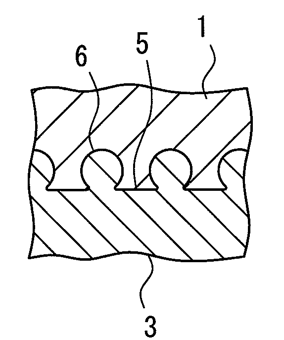
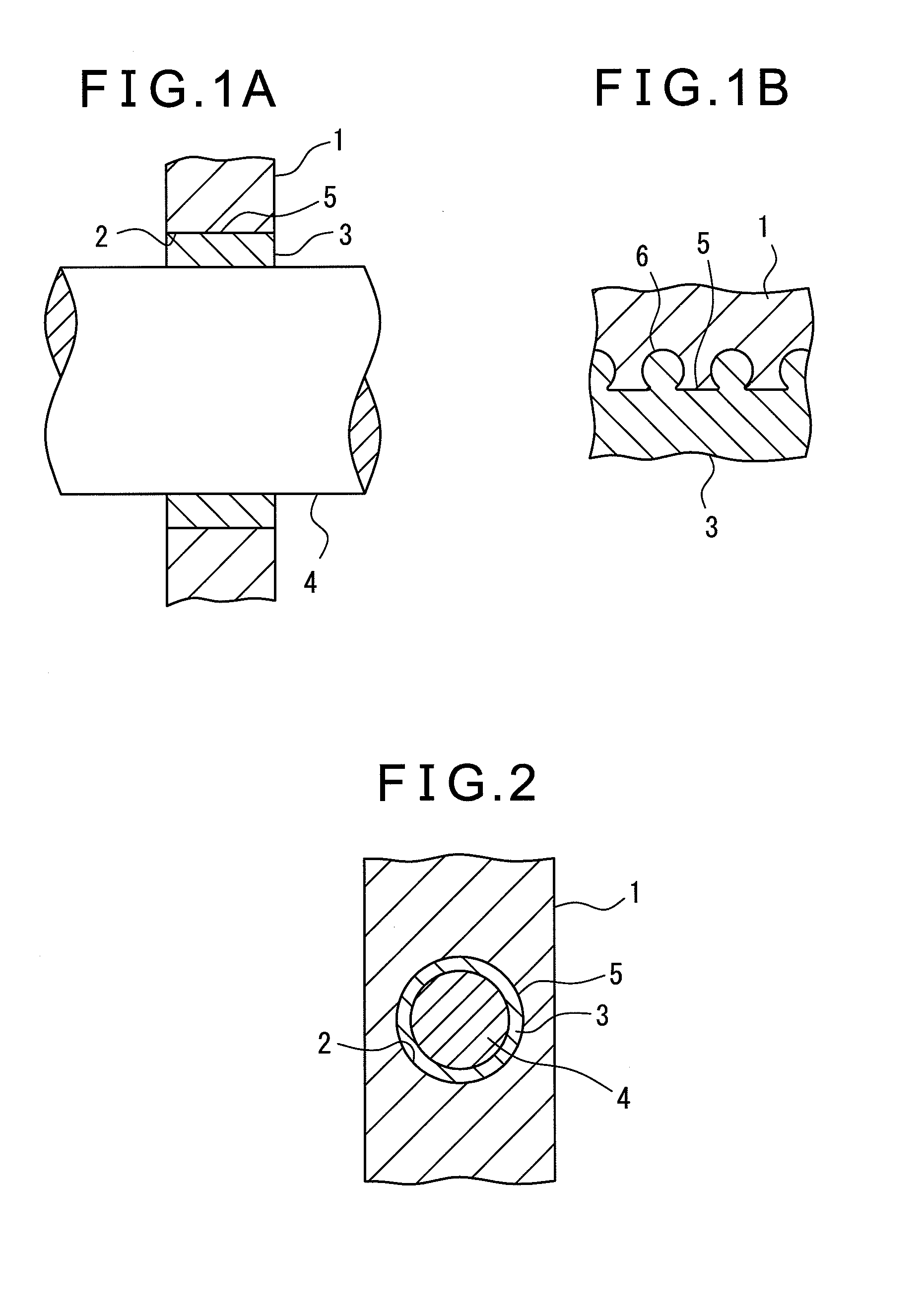
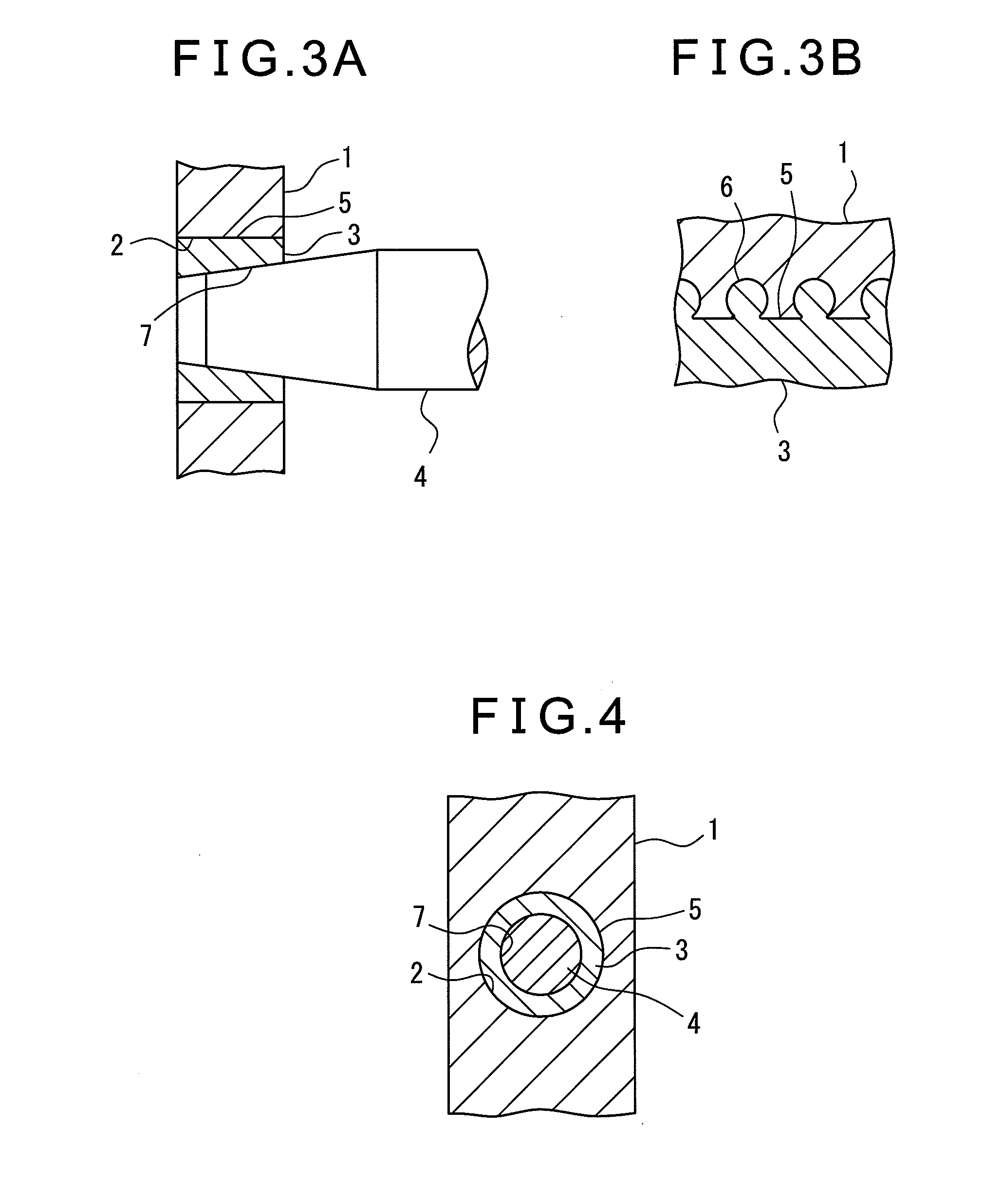
[0035]FIGS. 1A and 1B and FIG. 2 show an example where a support member directly supports a shaft. A metal outside member 1 is formed with a support hole 2. Inside this support hole 2, a metal support member comprised of a cylindrical tubular member 3 is attached. Inside the tubular member 3, a shaft 4 is supported in a rotatable manner.

[0036]The outside member 1 is made of aluminum, aluminum alloy, magnesium, or magnesium alloy. The tubular member 3 is attached to the support hole 2 of the outside member 1 by insert casting. The metal tubular member 3 is formed by cast iron, cast steel, copper, copper alloy, aluminum, aluminum alloy, magnesium, or magnesium alloy.

[0037]At the outer circumferential surface 5 of the tubular member 3, a plurality of projections 6 are formed over the entire area. Among the projections 6, part or all of the projections 6 are thin-waisted. The hei...


PUM

PropertyMeasurementUnit
Heightaaaaaaaaaa
Plasticityaaaaaaaaaa

Abstract

A support member with excellent contact with the member to which the support member is attached, that is, a metal support member which supports a shaft directly or through a bearing and which has a plurality of the projections at its outer circumferential surface, wherein the plurality of the projections are formed at the outer circumferential surface as a whole at the time of casting of the support member and wherein at least part of the projections have thin-waisted shapes or a plastic support member which supports a shaft directly or through a bearing and which has a plurality of the projections at its outer circumferential surface, wherein the plurality of the projections are formed at the outer circumferential surface as a whole at the time of molding of the support member and wherein at least part of the projections have thin-waisted shapes.

Description

[0001]This application claims benefit of Serial No. 2011-046192, filed 3 Mar. 2011 in Japan and which application is incorporated herein by reference. To the extent appropriate, a claim of priority is made of the above disclosed application.BACKGROUND OF THE INVENTION[0002]1. Field of the Invention[0003]The present invention relates to a support member which supports a rotary member directly or through a bearing.[0004]2. Description of the Related Art[0005]As a support member which supports a rotary member, for example the wear-preventing sleeve shown in Japanese Patent Publication (A) No. 10-131975 is known. This sleeve is attached by insert casting to a cast member provided with a support hole for supporting a rotary member and supports the rotary member in a sliding manner to prevent wear of the support hole. The sleeve is formed with several projecting parts at intervals in the outer circumferential surfaces so as to prevent it from being pulled out from the support hole of the ...

Claims


Application Information

Patent Timeline
IPC IPC(8): F16C33/06F16C33/20
CPCF16C33/08F16C35/02F16C33/06F16C33/12F16C33/208F16C35/077F16C2204/20F16C2220/02F16C2226/30F16C2240/40F16C9/04
Inventor KAMATA, KOJITAKANO, YUGO
Owner TEIKOKU PISTON RING CO LTD
Why Eureka
Try Eureka