Apparatus and method for rotating a fire, a flame, a smoke plume, or for circulating heat and candle assembly therefor
a technology of circulating heat and apparatus, which is applied in the direction of combustion process, fatty acid production, combustion ignition, etc., can solve the problems of device not being able to create the vortex solely, no regular movement, and no functionality, so as to facilitate accurate assembly and further adjust the device
- Summary
- Abstract
- Description
- Claims
- Application Information
AI Technical Summary
Benefits of technology
Problems solved by technology
Method used
Image
Examples
embodiment 50
[0076]FIG. 5A is a perspective view of an alternate embodiment 50 of the invention using a liquid or gas fuel and having a depression 52, in this case, an annular depression centered on the wick 36a, containing a fragrant oil. Instead of the candle flame 28 (i.e., a flame whose lower and upper portions do not move downwardly as the fuel is consumed, as in the case with a typical wax candle), a flame fueled by a liquid or gas has the advantage of a vertically stationary flame, thereby providing for consistent circular movement of the flame over the entire time that the flame is lit. Note as well that a buoyant candle (not shown) may be used which floats in a liquid such as water, which is provided in the cavity 20′ in which the candle is placed. Alternatively, magnets (not shown) having sides which face each other having the same polarization can be used to create a magnetic levitation of the candle, helping to keep the flame at the same level during the burning of the candle. A smal...
embodiment 60
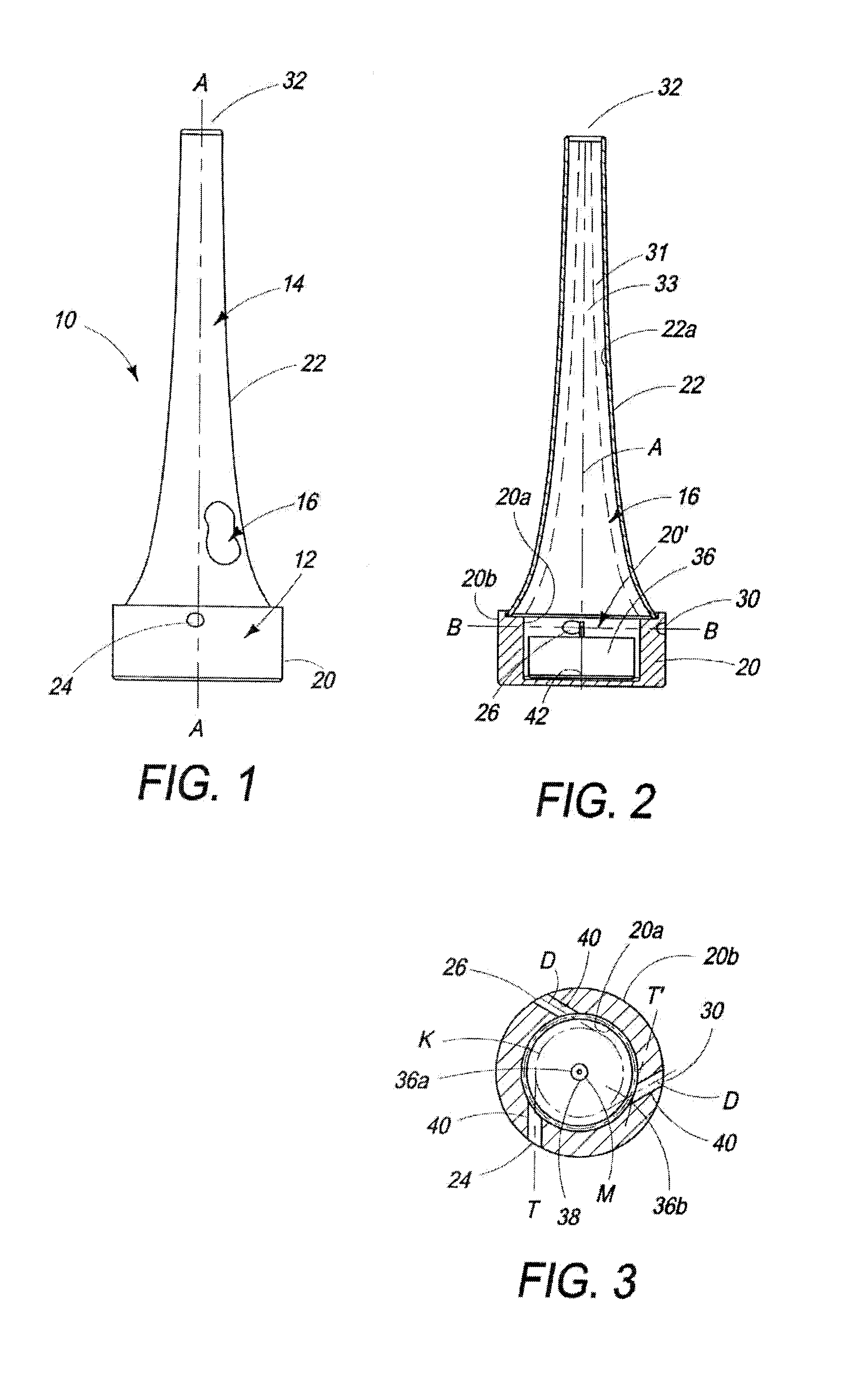
[0077]FIG. 6 is a cross sectional view of a second alternate embodiment 60 of the invention, made in a single piece, preferably by glass injection molding. An advantage of this embodiment is its simplicity in that it is composed essentially of a single chimney portion 62 in which holes 64 (corresponding to holes 24, 26 and 30) are formed. The lower portion 66 is open and so the device can be placed over a burning candle 68. In addition, using this embodiment, one can adjust the position of the candle very easily, to ensure that the flame remains at the center of the chamber 16′, simply by displacing the device, until the desired flame motion is obtained.
embodiment 70
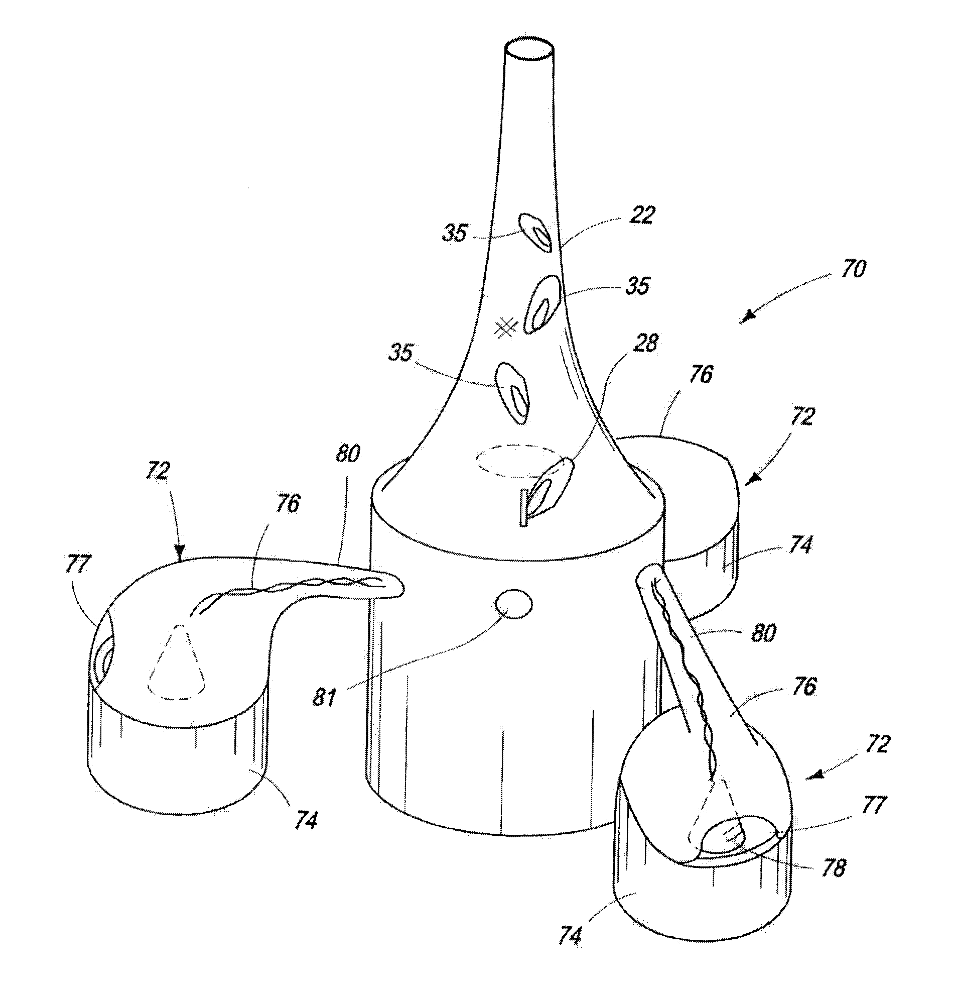
[0078]FIG. 7 is a perspective of view of a third alternate embodiment 70 of the invention, used to distribute smoke and / or fragrance from a plurality of satallitic incense burners 72. These incense burners 72 include a base portion 74 and a transparent cover portion 76 allowing an air inlet opening 77. The base portion 74 receives and contains the burning incense 78. The cover portion 76 directs the smoke and / or aroma of the incense through tube portions 80 which enter into the gas inlet openings 24, 26 and 30, thereby feeding the smoke or aroma into the chamber 22 where it is mixed by the revolving gases and then disbursed in the air through the gas outlet opening 32. Note that the height of the base portion 20 is increased in this embodiment to allow the tube portions 80 to enter at the level of the flame 28 (i.e., to allow for the height of the incense burners 72). Further, where additional oxygen is needed in such an arrangement, additional gas inlet opening / channels 81 can be p...
PUM
 Abstract
Description
Claims
Application Information
 - R&D
- Intellectual Property
- Life Sciences
- Materials
- Tech Scout
- Unparalleled Data Quality
- Higher Quality Content
- 60% Fewer Hallucinations
Browse by: Latest US Patents, China's latest patents, Technical Efficacy Thesaurus, Application Domain, Technology Topic, Popular Technical Reports.
© 2025 PatSnap. All rights reserved.Legal|Privacy policy|Modern Slavery Act Transparency Statement|Sitemap|About US| Contact US: help@patsnap.com


