Device for closing off an opening prepared in the roof of a vehicle, provided with a sealing barrier and a drain for draining water towards the exterior

a technology for openings and roofs, which is applied in the direction of roofs, mechanical devices, transportation and packaging, etc., can solve the problems of the glazed surface, etc., and affecting the sealing effect of the roof. , the effect of reducing the sealing

Inactive Publication Date: 2012-09-13
ADVANCED COMFORT SYST FRANCE ACS
View PDF2 Cites 7 Cited by
  • Summary
  • Abstract
  • Description
  • Claims
  • Application Information

AI Technical Summary

Benefits of technology

[0036]This approach makes it possible unexpectedly to ensure that the occupants of the vehicle will be protected from the splashing or falling of drops of water deposited on the external surface of the device and especially of the movable panel for example in the event of rain showers, because the device makes it possible to recover and drain this water towards the exterior of the vehicle in every position of opening of the movable panel.
[0037]Furthermore, in the closing-off position, the closing of the aperture prevents access to and therefore the filling of the water recovery and draining means which therefore remain fully efficient should the aperture be released. And even when a quantity of residual water unexpectedly penetrates the recovery and draining means, the device of an embodiment of the invention enables it to be drained to the exterior.

Problems solved by technology

This technique has the drawback of allowing for only a half opening of the roof in order to prevent it from being pulled away under the effect of aerodynamic pressure and of being capable of implementation only for small-sized windows glasses.
One drawback of this technique is that the dimensions of the apertures in the roof and therefore in the glazed surfaces enabling them to be closed off are limited.
One problem common to these sunroof techniques is that water, for example in the form of drops of condensation or rain, can penetrate the car interior space when the movable glass window or the sliding panel at least partially releases the aperture formed in the roof.
One drawback of this technique is that the receptacle may get completely filled and in certain cases overflow.
The excess water may then flow into the car interior space through the aperture, which of course is unsatisfactory.
It has been observed especially with these techniques that this drawback is amplified by the fact that the container can be filled above all with water outside periods when the sunroof is open, in other words when the sunroof is closed, which greatly reduces the efficiency of the container.
Another drawback of this technique is the need for the presence of a container for recovering water which reduces the window surface allowing light transmission and / or the permissible size of the opening on the exterior and / or the volume of the car interior space.
Yet another drawback of this technique and other prior-art sunroof techniques is that the elements designed to recover water can lower the aesthetic qualities of the vehicle.
One drawback of prior-art techniques providing for a draining of water is that they are generally complex to implement, especially when it is necessary to remove water deposited on the sliding glazed panel.
Yet another drawback of the prior-art techniques referred to here above is that, in certain cases, water can stagnate in the water recovery and or draining container, releasing an unpleasant odor.

Method used


Image

  • Device for closing off an opening prepared in the roof of a vehicle, provided with a sealing barrier and a drain for draining water towards the exterior
  • Device for closing off an opening prepared in the roof of a vehicle, provided with a sealing barrier and a drain for draining water towards the exterior
  • Device for closing off an opening prepared in the roof of a vehicle, provided with a sealing barrier and a drain for draining water towards the exterior

Examples


Embodiment Construction

1. Reminder of the Principle of an Embodiment of the Invention

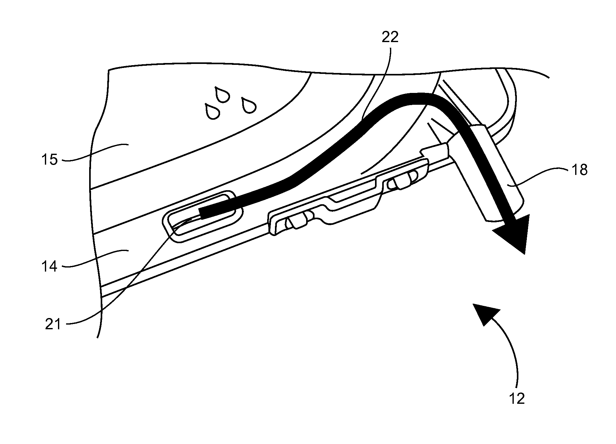
[0062]As referred to here above, the general principle of an embodiment of the invention therefore relies on the implementation of a draining of water that is deposited on the roof, on the external surface of the movable panel or on that of the fixed part, towards the exterior of the vehicle, as soon as the movable panel is in any opening position and hence as soon as the aperture is released, and solely in this case.

[0063]In at least one embodiment of the invention, this novel approach makes it possible especially to form an efficient sealing barrier for the aperture formed in the fixed part and therefore for the car interior space when the movable panel is closed.

2. Example of an Embodiment of the Invention

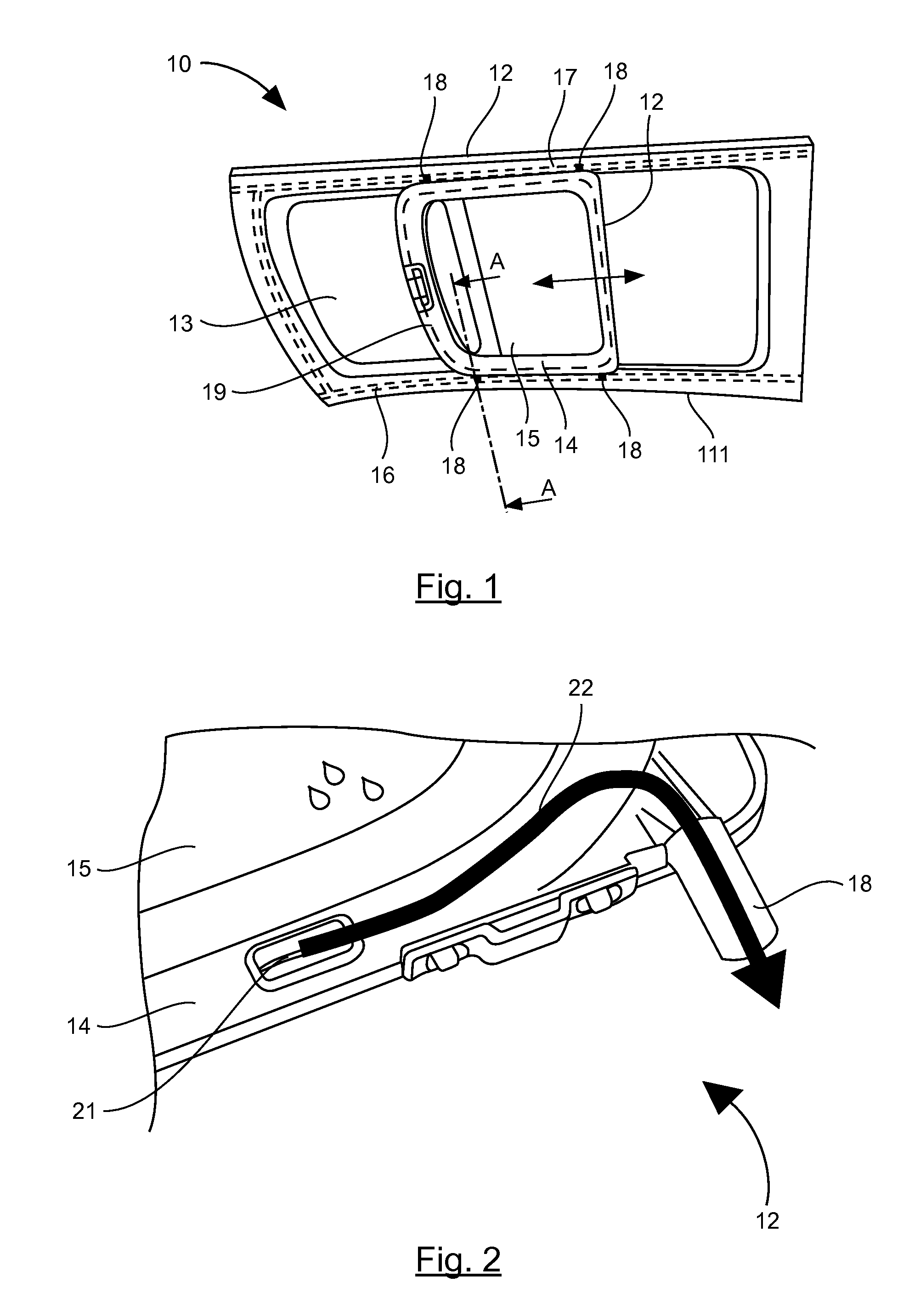
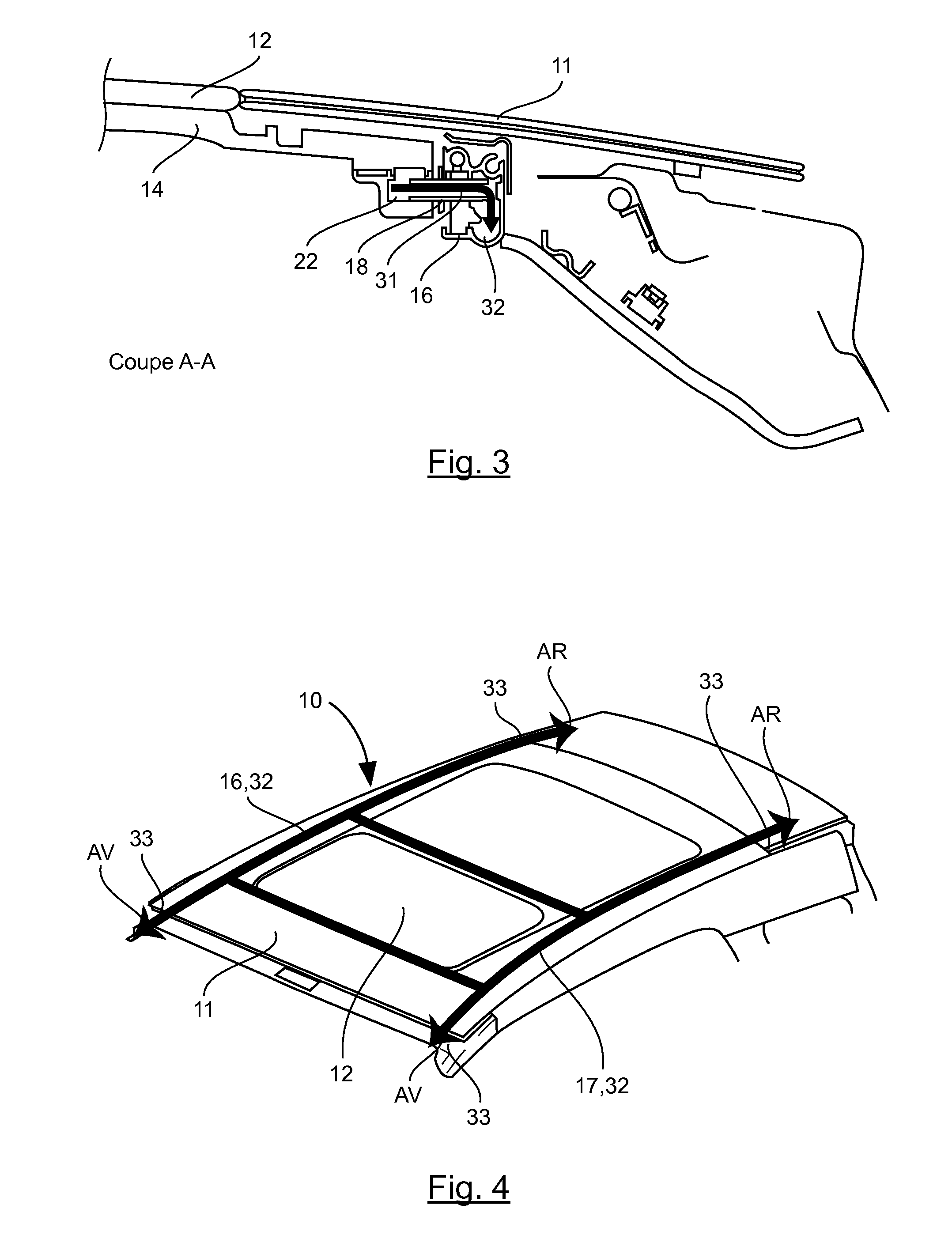
[0064]Here below, we consider a roof of a vehicle formed by a closing-off device according to an embodiment of the invention which is attached to the body of the roof of the vehicle.

[0065]FIG. 1 is an illustration, in...


PUM


Abstract

A device is provided for blocking an opening formed in an automobile roof, including a fixed glass portion to be rigidly connected to the vehicle and at least one glass panel. The glass panel is mobile relative to the fixed portion between a blocking position, in which it blocks an opening in the fixed portion, and at least one open position, in which the opening is at least partially open. Each of the mobile panels is slidingly guided along two rails rigidly connected to the surface of the fixed portion. The device also includes at least one passage for collecting and draining at least a portion of the water received on the outer surface of the mobile panel toward the outside of the vehicle. The passage is rigidly connected to the mobile panel to enable the water to flow from the mobile panel toward one of the rails.

Description

CROSS-REFERENCE TO RELATED APPLICATIONS[0001]This Application is a Section 371 National Stage Application of International Application No. PCT / EP2010 / 059509, filed Jul. 2, 2010, which is incorporated by reference in its entirety and published as WO 2011 / 045092 on Apr. 21, 2011, not in English.STATEMENT REGARDING FEDERALLY SPONSORED RESEARCH OR DEVELOPMENT[0002]None.THE NAMES OF PARTIES TO A JOINT RESEARCH AGREEMENT[0003]None.FIELD OF THE DISCLOSURE[0004]The field of the disclosure is that of the roofs of motor vehicles. More specifically, the disclosure pertains to window-fitted or glazed roofs comprising at least one aperture working with a sliding, movable glass panel or glazed panel.[0005]In the framework of the present application, the term “glazed panel” refers to any substantially transparent or translucent (fixed or movable) panel contributing to the window surface allowing light transmission, made out of glass or any other appropriate material such as polycarbonate. The edge...

Claims


Application Information

Patent Timeline
Patent Type & Authority Applications(United States)
IPC IPC(8): B60J7/043B60J10/12B60J10/82
CPCB60J7/0084B60J10/12B60J7/053B60J7/022B60J10/82
Inventor MALTAVERNE, GUYNEAUX, JEAN-CLAUDELEBOEUF, REGIS
Owner ADVANCED COMFORT SYST FRANCE ACS
Why Eureka
Try Eureka