
Variable energy management system for pedestrian, occupant, vehicle

a technology of energy management system and pedestrian, which is applied in the direction of pedestrian/occupant safety arrangement, braking system, tractors, etc., can solve the problems of inability to reset, damage other surrounding structures on the vehicle, and high price of the device, so as to reduce the injury of passengers, reduce the impact energy, and increase the thickness

Active Publication Date: 2010-10-12
SHAPE CORP
View PDF66 Cites 10 Cited by
  • Summary
  • Abstract
  • Description
  • Claims
  • Application Information

AI Technical Summary

Benefits of technology

The present invention provides an energy-absorbing system for vehicles that can protect passengers from injury during crashes. The system includes an energy-absorbing component that can change its shape based on the severity and location of the crash, allowing for a more effective absorption of impact energy without sacrificing space during normal operating conditions. The energy-absorbing component can be shaped to cover a portion of the interior surface of a structural component, such as a seat belt or air bag, and absorb energy based on the rate of impact. The system can also include activators and controllers to vary the level of impact resistance and protect passengers from injury during different types of crashes. Overall, the invention provides a more effective and flexible approach to protect passengers from injury during crashes.

Problems solved by technology

These devices are very expensive and cannot be reset.
Once deployed, they must be completely replaced and oftentimes can damage other surrounding structures on the vehicle.
In addition, they are fairly finite in nature, i.e., placed in specific locations, which cannot account for every type of impact situation.

Method used


Image

  • Variable energy management system for pedestrian, occupant, vehicle
  • Variable energy management system for pedestrian, occupant, vehicle
  • Variable energy management system for pedestrian, occupant, vehicle

Examples


Embodiment Construction

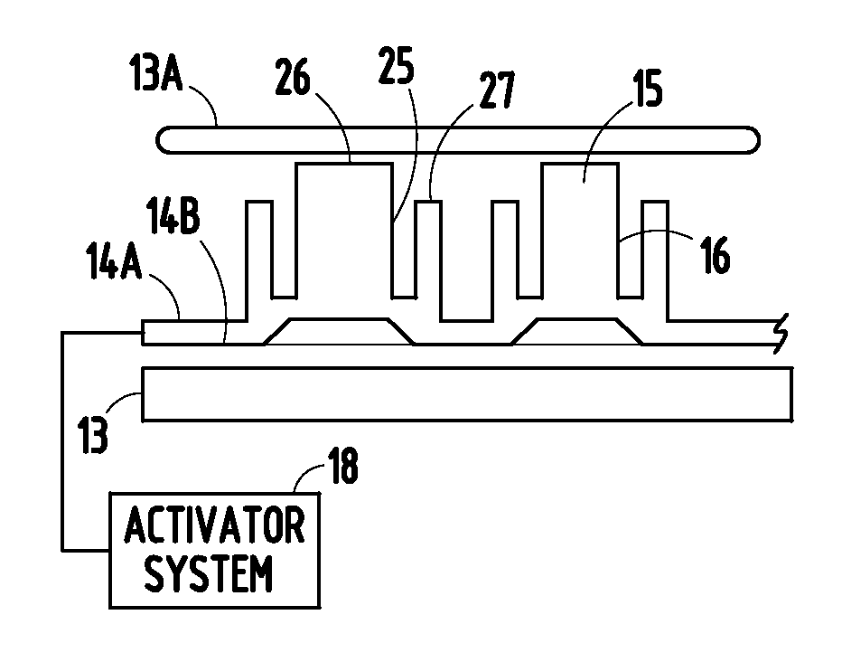
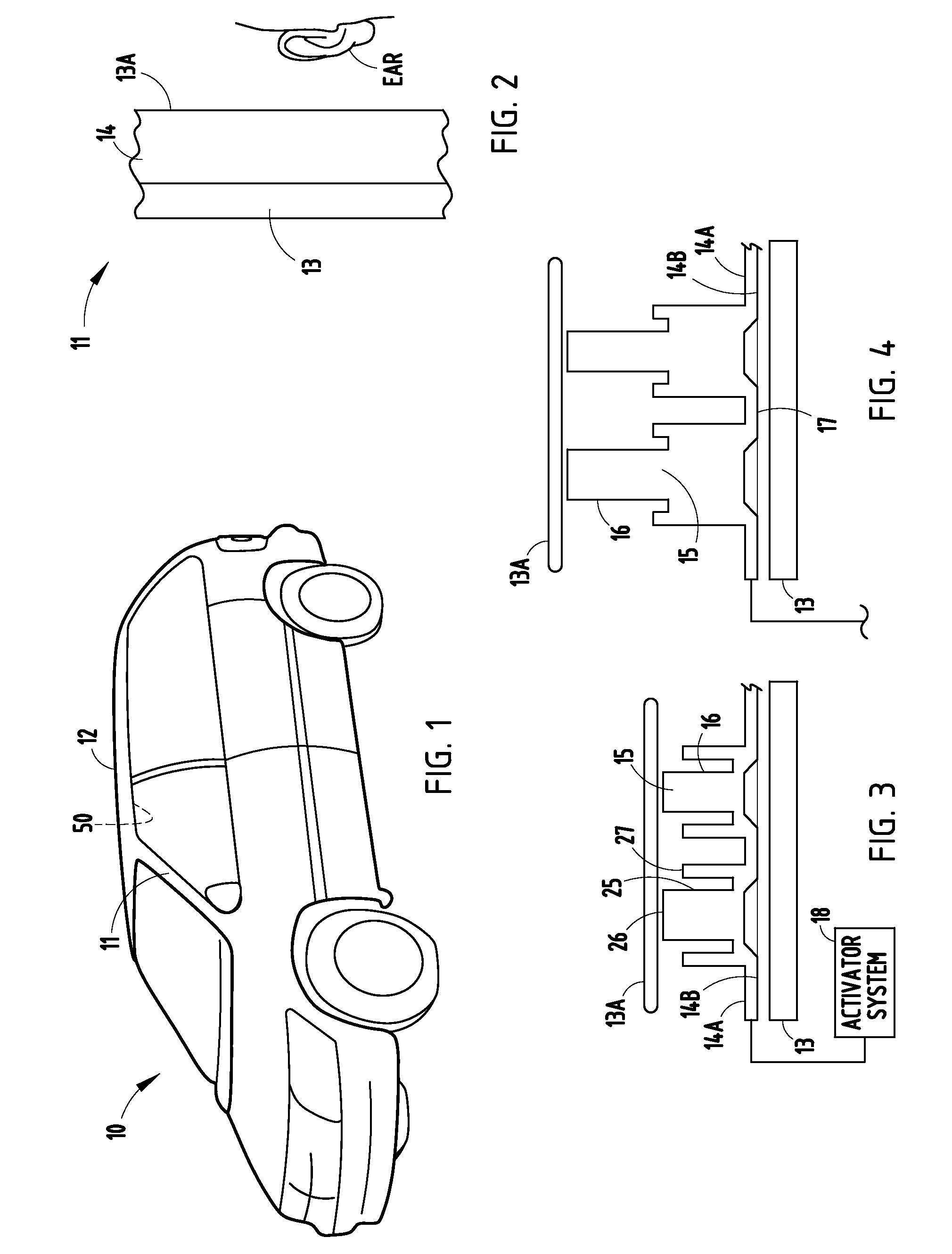
[0050]A vehicle 10 (FIG. 1) includes an “A” pillar 11 that along with other pillars supports a roof 12. The illustrated “A” pillar 11 includes a vertically-extending structural metal beam 13, a trim cover 13A aesthetically covering a visible part of the interior surface of the beam 13, and an energy-absorbing sheet component 14 positioned between the beam 13 and trim cover 13A. The component 14 can be integral with or separate from the cover 13A. The illustrated component 14 comprises a pair of thermoformed polymeric sheets 14A and 14B bonded or sealed together (see FIGS. 3-4) to define air-trapping cavities 15 within crush boxes 16 (also called “crush cans” and / or “internal structure” adapted to absorb energy, such as if a passenger's head impacts the “A” pillar during a vehicle crash). It is noted that the energy absorber could also be made by blow-molding or by adhering a thermoformed sheet to a second surface (such as to the trim cover 13A or to the structural part / pillar 11). A...


PUM


Abstract

An energy-absorbing system includes two formed and sealed components bonded together to form crush boxes that entrap air for controlled distribution during an impact, and an activator system adapted to extend the crush boxes in the event of a vehicle crash. Channels interconnect the crush boxes for optimal control of lateral flow of air for lateral energy distribution. The components can be thermoformed, injection molded, or otherwise formed. By this arrangement, the crush boxes provide a first level of static energy absorption when impacted in an undeployed state such that energy is absorbed at a first rate and stroke. Also, the crush boxes can be extended to provide a second level of static energy absorption when impacted in a vehicle crash (i.e., the activator system is energized and the crush boxes extended or “deployed”) such that energy is absorbed at a one or more different rates and strokes.

Description

CROSS REFERENCE TO RELATED APPLICATION[0001]This application claims benefit under 35 U.S.C. §119(e) of co-assigned provisional application Ser. No. 60 / 739,508, filed Nov. 23, 2005, entitled IMPACT ENERGY ABSORBER WITH ACTIVE AND PASSIVE ASPECTS, the entire contents of which are incorporated herein in their entirety.BACKGROUND[0002]The present invention relates to components and systems adapted for variable absorption of impact energy, and more specifically relates to an energy absorber for use on front and rear bumpers of vehicles and in the passenger compartment of vehicles, such as on the interior surface of structural roof pillars, headliners, interior door panels, instrument panels, and other places where impact absorption is an important feature of the component. It is contemplated that a scope of the present invention is not limited to automobiles, nor to only passenger vehicles.[0003]It is difficult to reduce vehicle size while also maintaining a comfortable amount of interna...

Claims


Application Information

Patent Timeline
Patent Type & Authority Patents(United States)
IPC IPC(8): B60K28/10
CPCB60R21/045B60R21/0428B60R2021/0414B60R2021/0435B60R2021/346
Inventor EVANS, DARIN
Owner SHAPE CORP
Learn More