Eureka AIR delivers breakthrough ideas for toughest innovation challenges, trusted by R&D personnel around the world.

Electric power generation device and electronic instrument

Active Publication Date: 2012-09-13
CASIO COMPUTER CO LTD
View PDF6 Cites 9 Cited by
  • Summary
  • Abstract
  • Description
  • Claims
  • Application Information

AI Technical Summary

Problems solved by technology

Hence, only a very small part of the electric flux lines goes toward the operation electrodes 1 as important targets, and accordingly, the electric charges induced to the operation electrodes 1 are very small in comparison with those induced to the underlying electrode 2, and there has been a problem that surface electric charges of the electrets 3 cannot be utilized effectively.
Hence, it becomes difficult to charge the electrets 3, and there has been a problem that it is difficult to increase the electric power generation amount since a high surface potential cannot be applied to the electrets 3.
Moreover, problems described as follows have been inherent in the electret electric power generation device (electric power generation device of electrostatic induction type) of the conventional technology.Since the operation electrodes 1 are formed into the comb teeth shape, a surface area of surfaces of the operation electrodes 1 which generate the induced electric charges, the surfaces being opposed to the electrets 3, is reduced, and electric power generation efficiency with respect to a device area is poor.It is necessary to draw wires from the operation electrodes 1 which move in a vibration manner, and a device structure becomes complicated in order to stably take out electric power.As understood from the general formulae (1) and (2), a narrower gap (d1) between the electrets 3 and the operation electrodes 1 brings about a large effect for the electric power generation.
Therefore, the device structure becomes complicated.

Method used


Image

  • Electric power generation device and electronic instrument
  • Electric power generation device and electronic instrument
  • Electric power generation device and electronic instrument

Examples


Embodiment Construction

[0054]Embodiments of the present invention will be explained with reference to the drawings.

[0055]A description is made below of details of an electric power generation device according to the present invention. Note that, though a variety of technically preferable limitations are imposed on embodiments to be described below for the purpose of embodying the present invention, the scope of the invention is not limited to the following embodiments and illustrated examples.

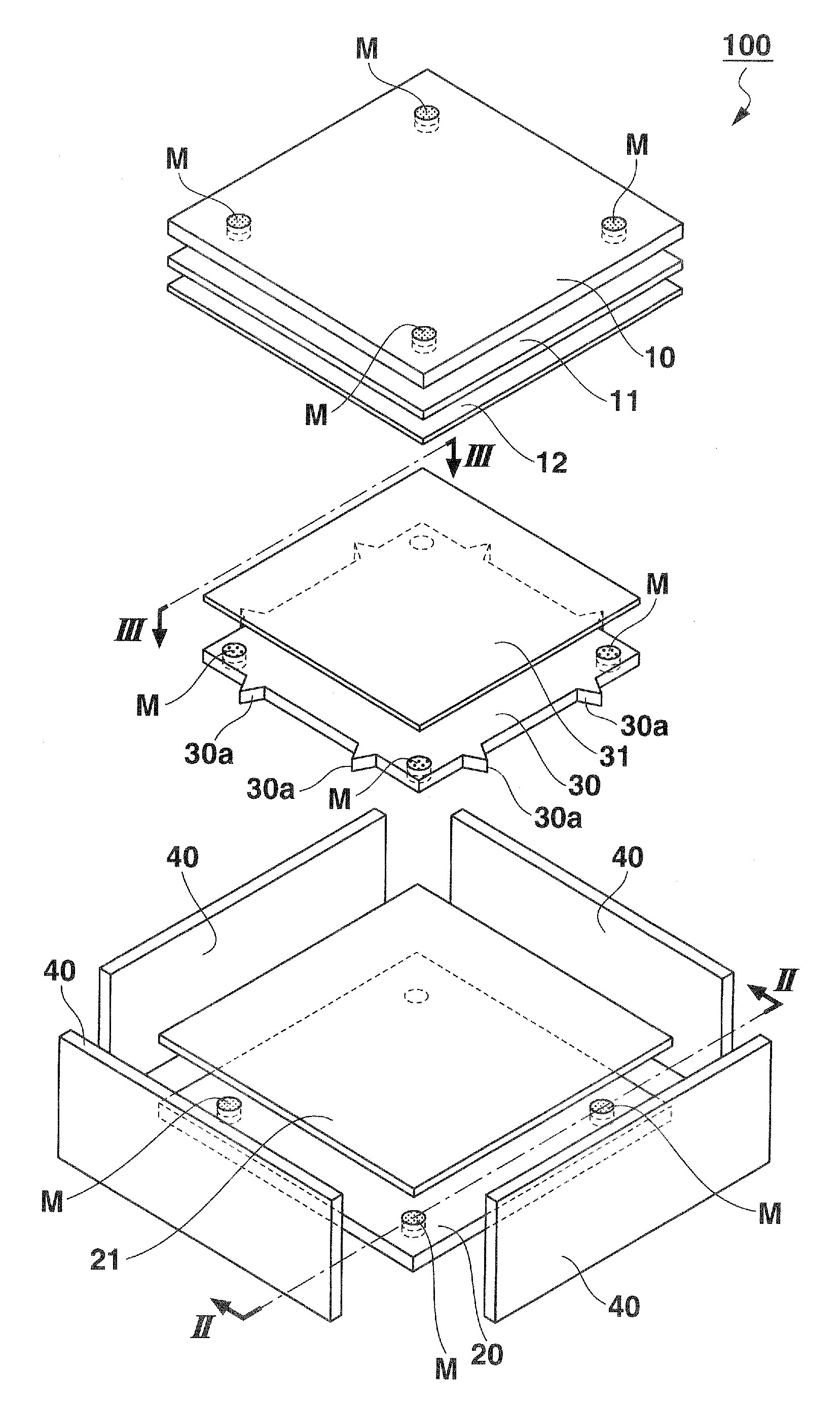
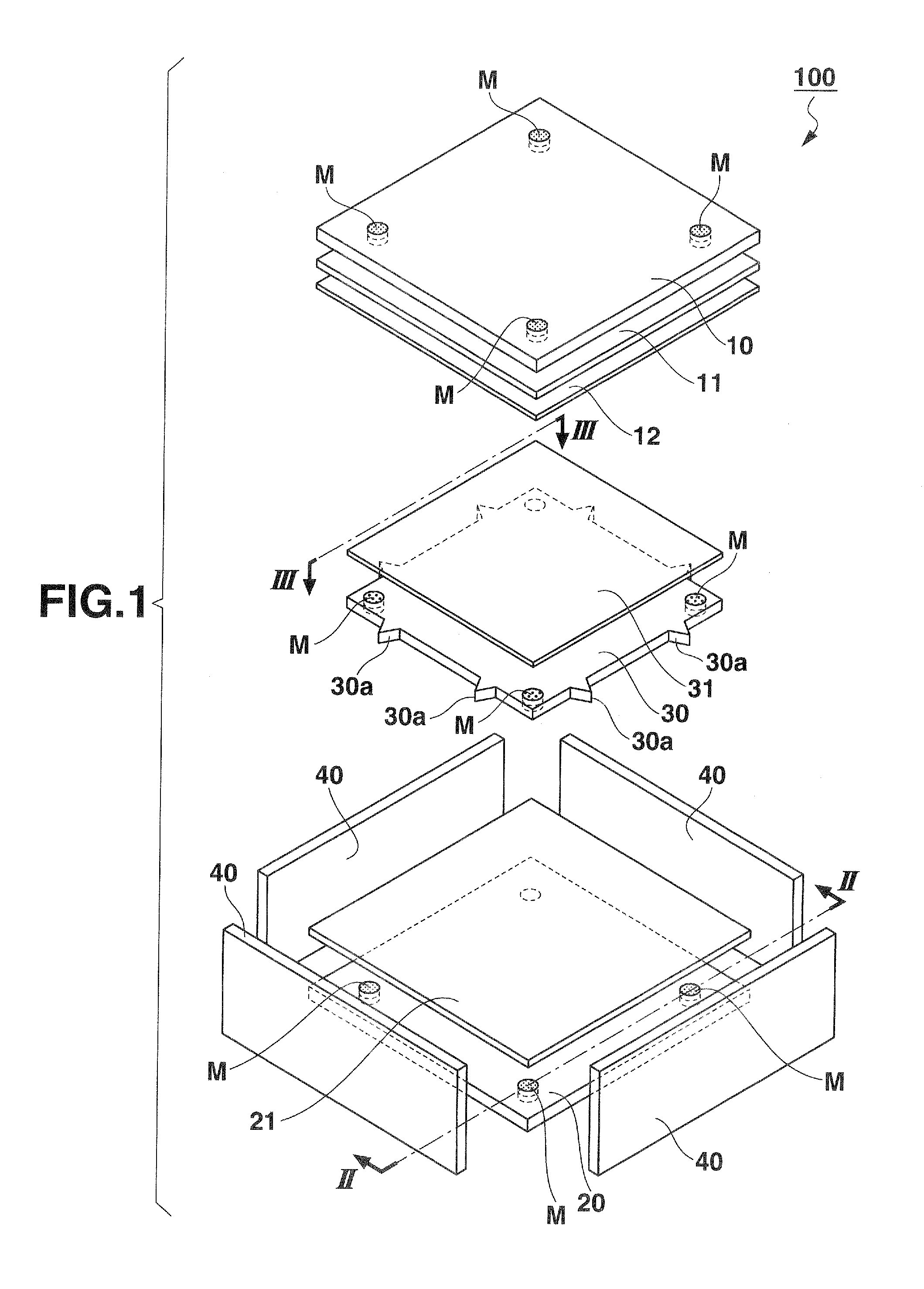
[0056]FIG. 1 is an exploded perspective view showing an electric power generation device according to the present invention.

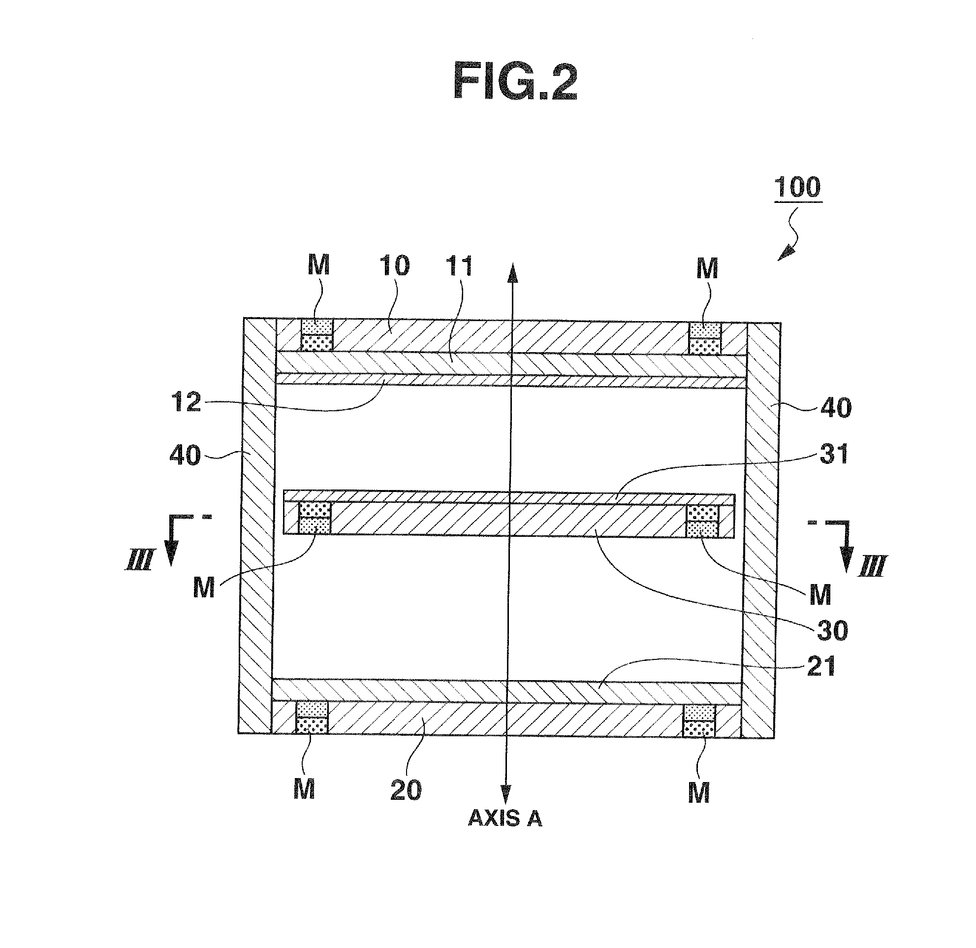
[0057]FIG. 2 is a longitudinal cross-sectional view showing the electric power generation device, taken along a cutting plane line II-II of FIG. 1. FIG. 3 is a lateral cross-sectional view showing the electric power generation device, taken along a cutting plane line III-III of FIG. 1.

[0058]As shown in FIGS. 1 to 3, an electric power generation device 100 is a device, in which an outer frame (fr...


PUM


Abstract

Disclosed is an electric power generation device comprising: a pair of electrodes arranged opposite to each other; and an electret member that is arranged between the pair of electrodes to be spaced apart from the pair of electrodes, and is provided to be movable in a direction of a perpendicular axis passing through the pair of electrodes.

Description

CROSS-REFERENCE TO RELATED APPLICATIONS[0001]This application is based upon and claims the benefit of priority under 35 USC 119 of Japanese Patent Application Nos. 2011-051225 and 2011-270790, the entire disclosure of which, including the description, claims, drawings, and abstract, is incorporated herein by reference in its entirety.BACKGROUND OF THE INVENTION[0002]1. Field of the Invention[0003]The present invention relates to an electric power generation device and to an electronic instrument using the same.[0004]2. Background Art[0005]Heretofore, an electric power generation device of an electrostatic induction type has been known, in which strap-like electrets and comb teeth-like operation electrodes are arranged opposite to each other, and the operation electrodes vibrate in a horizontal direction with respect to the electrets, whereby electric power generation by electrostatic induction is enabled (for example, refer to Japanese Patent Laid-Open Publication No. 2006-180450).[...

Claims


Application Information

Patent Timeline
IPC IPC(8): H01G7/02
CPCH02N1/08H02J7/34H02J1/12
Inventor UESUGI, YOSHINORI
Owner CASIO COMPUTER CO LTD
Why Eureka
Eureka Blog
Learn More