Vapor-tight lighting fixture

a technology of lighting fixtures and vapor seals, which is applied in the direction of gas-filled discharge tubes, gas-tight/water-tight arrangements, electric circuit arrangements, etc., can solve the problems of aging, fading of the lens, and eventual failure of wiring and electronics, so as to eliminate cumulative thermal load, easy and individually accessible for service, and easy to remove and repla

Inactive Publication Date: 2012-09-13
GREENDOT TECH
View PDF14 Cites 50 Cited by
  • Summary
  • Abstract
  • Description
  • Claims
  • Application Information

AI Technical Summary

Benefits of technology

[0006]This invention overcomes disadvantages of the prior art by providing a vapor-tight luminaire that is suitable for installation in open or moist environments, such as parking garages, that maintains a moisture-proof, sealed lower housing for the light-producing lamps (fluorescent lights, LED arrays, etc.) while isolating the electronic components, such as fluorescent ballasts, LED drivers and other devices in a separate, moisture proof upper housing that is spaced apart from, and largely thermally isolated from, the lamps. This isolating arrangement eliminates the cumulative thermal load that will ultimately degrade the efficiency off the luminaire and its associated component life. Likewise, the luminaires internal components (lamp assembly, electronics, etc.) are readily and individually accessible for service, replacement or retrofit by individually accessing each of a plurality of respective housings within the overall luminaire. The lamp housing comprises a unitary tubular lens with one or more removable end caps, sealed by gaskets. The lamp assembly is slidably mounted within the lower housing so that it is readily removable and replaceable with another assembly of the same or different type. The electronics in the upper housing is readily accessible and replaceable by removing a top cover that encloses a three sided channel member. The upper housing is illustratively metal, and desirably enhances heat exchange with the environment. The two housings are held together in a predetermined orientation by a pair of opposing end cap structures that include a housing end structure (that can be cast, machined or otherwise constructed) and a removable end cap. The use of vertically oriented sealing surfaces at each end of the luminaire inherently provides improved sealing capability due to (a) greatly reduced sealing surface area as opposed to traditional horizontally sealed luminaires; (b) greatly reduced spacing between end cap fasteners which create the seal condition, and notably, (c) by providing vertically oriented sealing surfaces that limit the possibility for moisture to migrate into the luminaire as gravity causes moisture to ‘drain’ off of the luminaire, and not accumulate on and / or seep through the seal.
[0007]The housing end includes an upper plate that is fastened against an adjacent end of the upper housing's channel member. This compresses gaskets that stand between the respective ends of the lens and a lower ring on each housing end with a substantially uniform pressure about the entire perimeter, enabling a more reliable and even seal. The electronics of the upper housing is interconnected via a connector to an end connector in on the lamp assembly. The interconnection can reside in a volume defined by a dome in at least one of the end caps, which can be light transmissive. The interconnection can include an interconnecting wiring harness (i.e. a multi-conductor cable) that exits the upper housing through a wire-chase hole in the upper plate of the housing end and reenters the housing end through another wire-chase hole adjacent to the tubular lens, near the lower ring. A removable covering cap with an associated gasket covers the exposed portion of the interconnecting harness where it extends between the upper housing and the lower housing. This covering cap and gasket defines an L-shaped surface that engages against the corresponding L-shaped surfaces of the housing end in the region of the wire-chase holes. A similar covering cap and gasket is located on the opposing housing end as well. This covering cap can be substituted by an accessory, such as an external controller, sensor, or other functional device / feature. The accessory can be located on the housing end that contains the lamp assembly harness, or on the opposing housing end. The wire-chase holes in the housing end that access either (or both) of the housings (upper and / or lower) can be employed to guide an accessory harness that interconnects with electronics contained within the housing(s). The accessory can include an integral cover and associated gasket to seal off the chase holes.

Problems solved by technology

However, the seal is subject to the effects of aging, and eventually fails over time.
This is partially the result of the spacing between sealing clamps and the elongated nature of the horizontal sealing surface (which provides an uneven compression to the joint line) combined with aging of the materials, environmental changes and extremes in temperature.
As the seal degrades it allows for the undesirable infiltration of moisture and contaminants.
Once the moisture enters, it pools in the lens, causing fogging, staining of the lens and eventual failure of the wiring and electronics.
Shortened lamp and electronics (ballast, etc.) life due to moisture-based deterioration increases the costs of maintaining the luminaires, and shortened unit life leads to more frequent replacements and higher costs for the facility owner / operator.
This arrangement makes it difficult to access and service the electronics, as they are generally placed beneath the lamp assembly, requiring removal of a significant portion of the internal components to replace a ballast or other electronic element of the luminaire.
Even where servicibility is a secondary concern, the placment of both the electronics and the lamp assembly in a single overall, sealed enclosure can prove problematic where certain types of lamps (e.g. LEDs or incandescent) or electronics generate sognificant heat, and that heat is essentially trapped within the sealed housing, degrading the internal components and potentially degrading the seal through heat damage.

Method used


Image

  • Vapor-tight lighting fixture
  • Vapor-tight lighting fixture
  • Vapor-tight lighting fixture

Examples


Embodiment Construction

[0034]I. Structural Overview

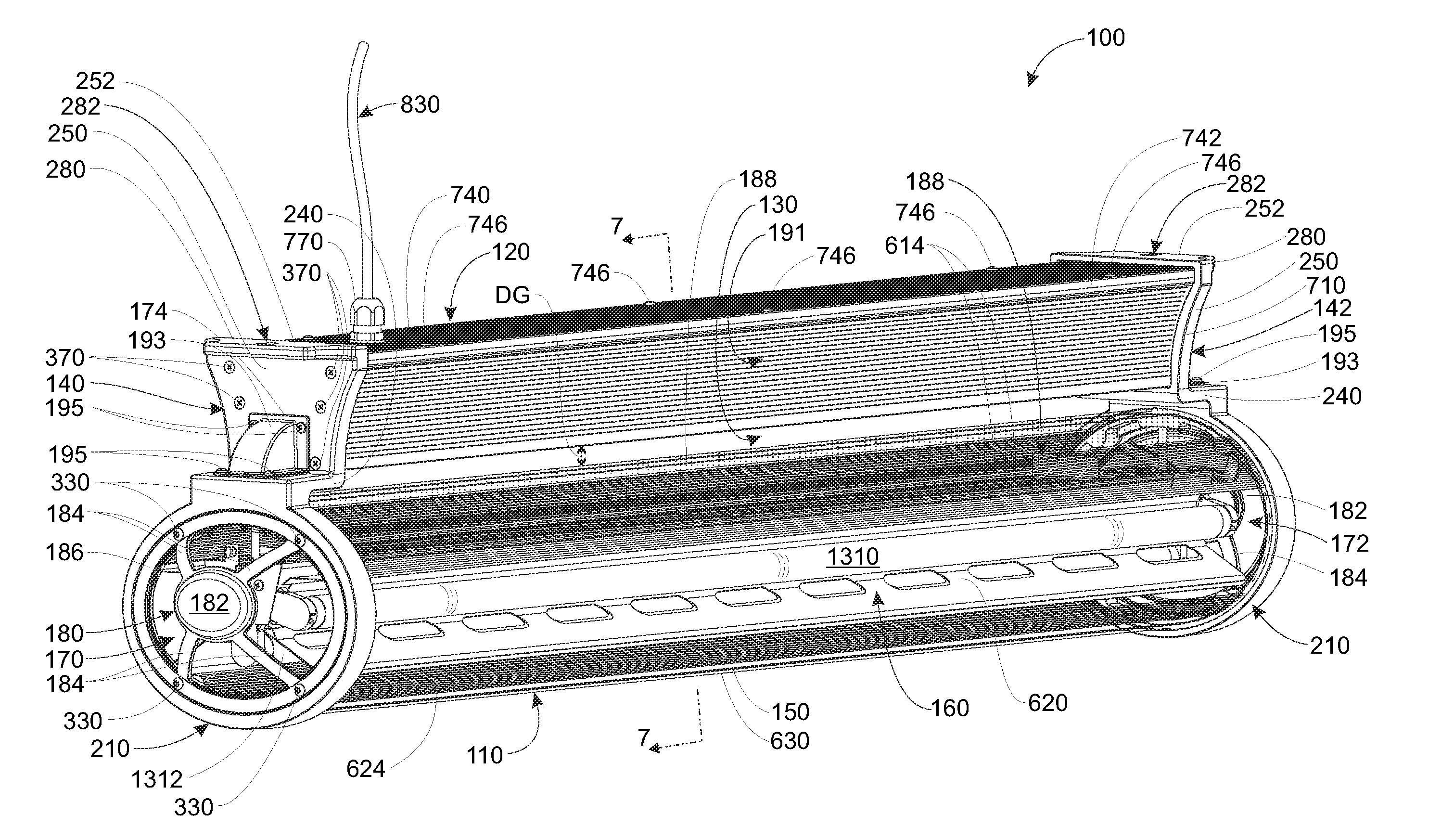
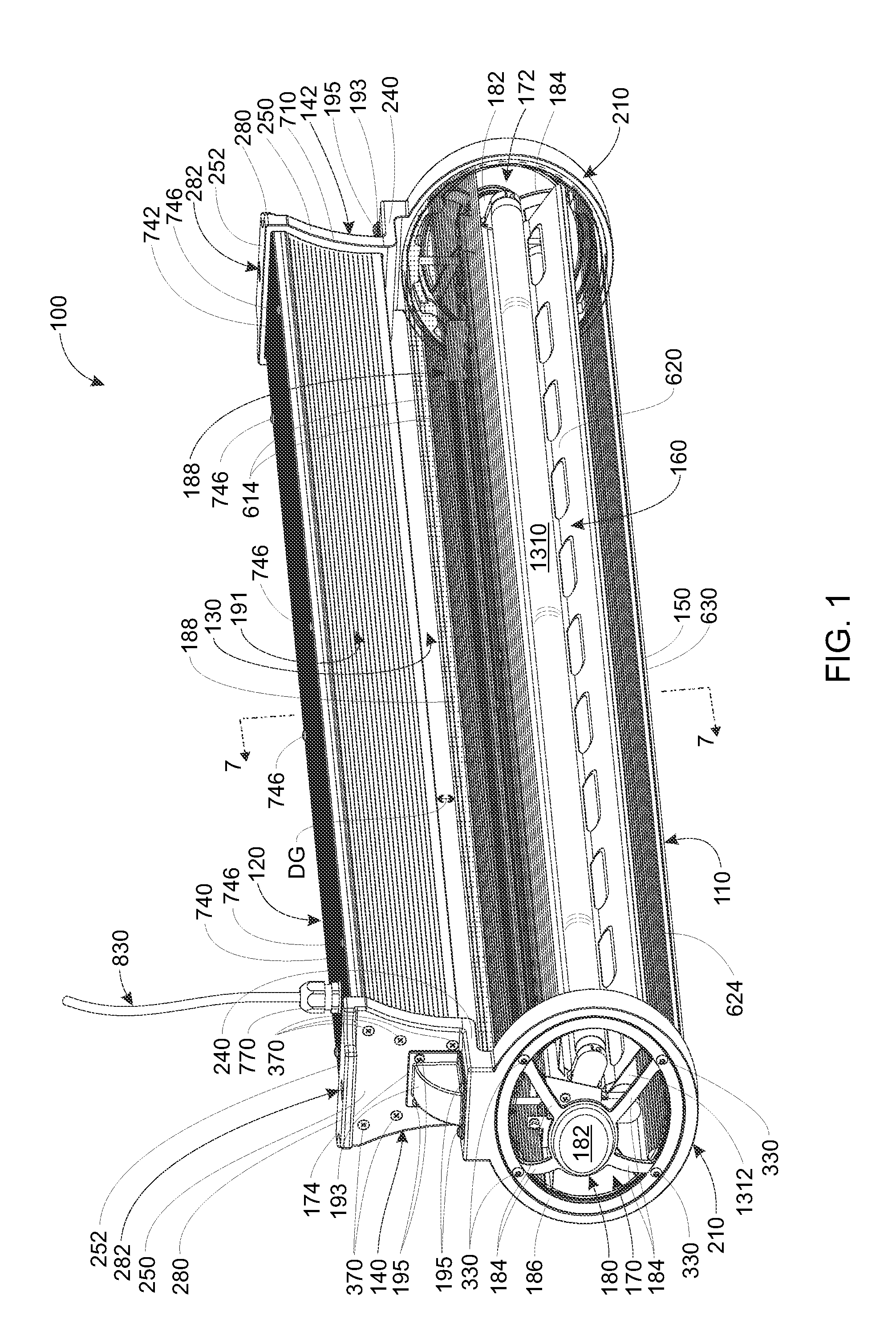
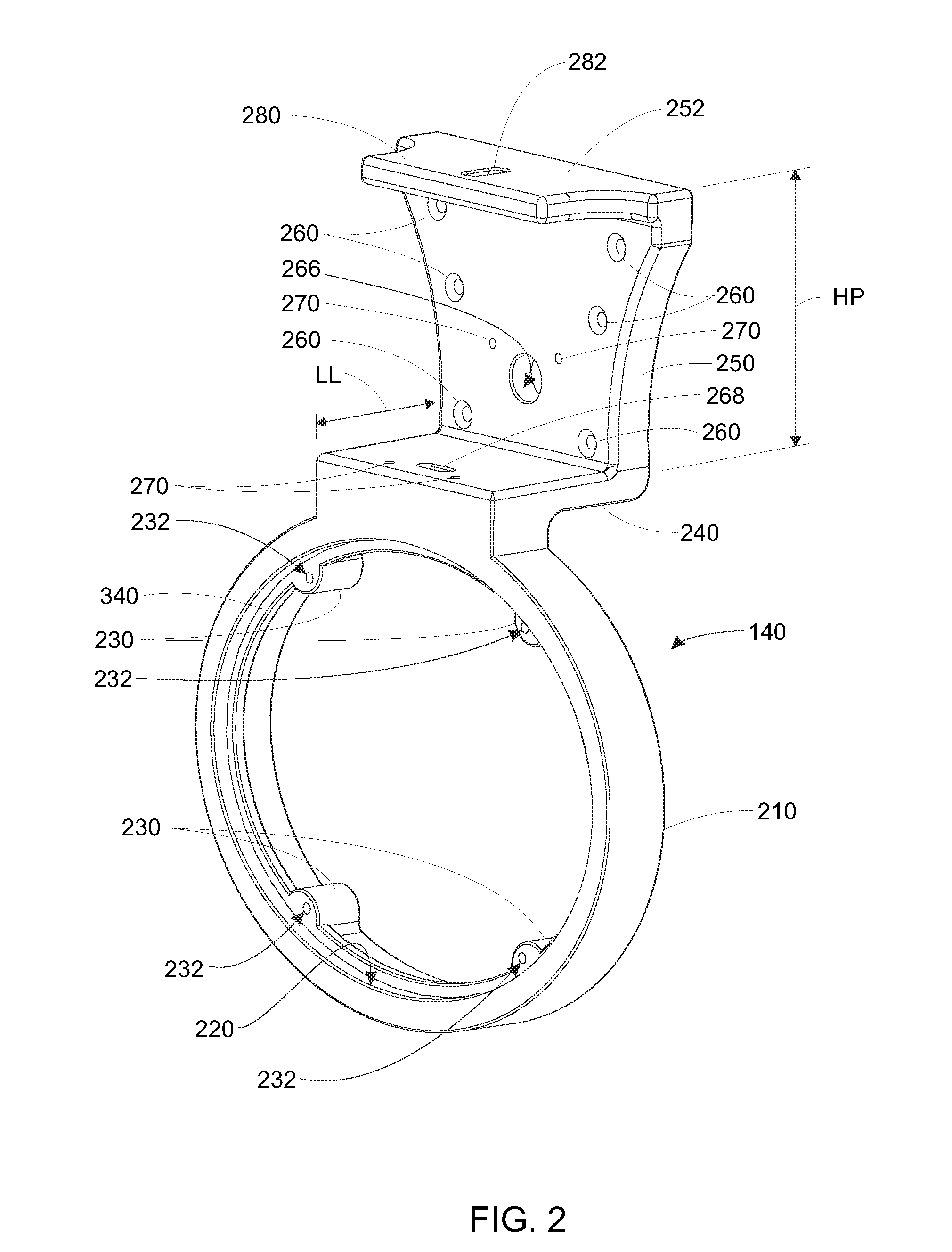
[0035]A luminaire (light fixture) according to an illustrative embodiment is shown in assembled form in FIG. 1 and in exploded view (with reflector and lamp assembly omitted) in FIG. 3. This novel luminaire 100 includes a main light source housing 110 (also termed “main housing” or “lower housing”) and an electronics and / or ballast housing 120 (also termed “upper housing”) that is suspended above and separated from the main housing 110 with a gap or airspace 130 that runs the length of each housing between opposing housing end structures (or “housing ends”) 140 and 142. The housing ends 140, 142, maintain the alignment between the upper and lower housings and provide the units overall structural integrity as described further below. Illustratively, the gap 130 has a vertical distance DG between the confronting housing surfaces of approximately ¼ to 1½ inches. Other gap distances are expressly contemplated. The gap is generally small enough to prevent wild...


PUM

PropertyMeasurementUnit
thicknessaaaaaaaaaa
lengthaaaaaaaaaa
thicknessaaaaaaaaaa

Abstract

This invention provides a vapor-tight luminaire that maintains a moisture-proof, sealed lower housing for the light-producing lamps (fluorescent lights, LED arrays, etc.) while isolating the electronic components in a separate, upper housing that is spaced apart from, and largely thermally isolated from, the lamps. The lamp housing comprises a unitary non-penetrated tubular lens with one or more removable end caps, sealed by gaskets. The lamp assembly is slidably mounted within the lower housing so that it is readily removable and replaceable with another assembly of the same or different type. The electronics in the upper housing is readily accessible and replaceable by removing a top cover that encloses a three sided channel member. The upper housing is metal and desirably enhances heat exchange with the environment. The two housings are held together by a pair of opposing end cap structures that include a housing end and a removable end cap. The housing end includes an upper plate that is fastened against an adjacent end of the upper housing's channel member. This compresses gaskets that stand between the respective ends of the lens and a lower ring on each housing end. The electronics of the upper housing is interconnected via a wiring harness connector to an end connector in on the lamp assembly. The wiring harness passes between the two housings free of penetration of the lens.

Description

FIELD OF THE INVENTION[0001]This invention relates to lighting fixtures / luminaires for commercial and industrial applications and more particularly to high-energy-efficiency lighting fixtures.BACKGROUND OF THE INVENTION[0002]Traditional high-intensity luminaires (also popularly termed “fixtures”) for installation in various indoor, outdoor and indoor / outdoor (e.g. parking areas) environments are weatherproof, having durable sealed lens covers that keep moisture, vapor and other contaminants away from their internal lamps, wiring and electrical components. Such luminaires are commonly termed “vapor-tight” fixtures / luminaires. These luminaires generally include a fluorescent lamp assembly within their housing. Currently available designs define a “clamshell” consisting of an elongated, opaque, upper box (typically of polymer material), having pendant mounting brackets, attached electronics (ballast, etc.), wiring, reflector assembly and a plurality of fluorescent lamps in a predetermi...

Claims


Application Information

Patent Timeline
Patent Type & Authority Applications(United States)
IPC IPC(8): H01J13/46H05K13/00H05B37/02H01K1/30H01J1/62
CPCH05B33/0803F21V31/00F21V15/015F21Y2101/02Y10T29/49002F21Y2103/00F21Y2103/003F21Y2113/00F21S8/043F21Y2103/10F21Y2115/10H05B45/3578
Inventor EDWARDS, JR., RICHARD D.KATZ, STANLEY A.
Owner GREENDOT TECH
Why Eureka
Try Eureka