Battery pack with safety device, control device and control method

a technology of safety device and battery pack, applied in the direction of battery/fuel cell control arrangement, electric vehicle, battery/cell propulsion, etc., can solve the problems of high voltage becoming a hazard to people or equipment, and the document does not address the problem of high voltage risks, so as to achieve the effect of reducing the problem of high risks

Inactive Publication Date: 2012-09-13
HDD SERVO MOTORS
View PDF3 Cites 103 Cited by
  • Summary
  • Abstract
  • Description
  • Claims
  • Application Information

AI Technical Summary

Benefits of technology

[0006]One object of the present invention is to alleviate the problems of high risks in conjunction with using high voltages for devices powered by a battery pack.
[0011]By providing a battery pack comprising at least one battery cell and a battery control circuit adapted to receive an operate control signal indicating that a load is to perform its function, and to allow feeding the supply of voltage from the battery cell through the battery control circuit in response to the operate control signal, it is possible to supply the voltage through the battery control circuit primarily when the load is in actual operation. Hence the time during which voltage is supplied through the battery control circuit can be limited, decreasing the risk of high voltages.
[0012]Preferably, the battery control circuit also avoids feeding the supplied voltage through the battery control circuit in response to receiving information that the load is in a non-operating state. Preferably, the reception of information that the load is in a non-operating state also encompass an absence of a signal that the load is in an operating state. Hence in case the load is not actively performing its function, the voltage supplied through the battery control circuit may be decreased or cut-off entirely, decreasing the time during which a high voltage is supplied and substantially improving the safety of using the battery pack.
[0015]According to one embodiment of the invention the battery control circuit comprises a semi-conductor device comprising a first connector electrically connected with at least one battery cell, a second connector, and a switch control arranged to allow a current between the first and the second connectors when receiving a control voltage. Preferably the control voltage is received from the operate control signal. Preferably the semi-conductor device is a FET-device, such as a MOS-FET, or an IGBT. Such devices are naturally cut-off unless receiving a voltage signal at the gate. Thus the features of the invention may be achieved easily and inexpensively by use of the semiconductor device.

Problems solved by technology

One problem with battery packs having many battery cells connected in series is that the voltage may be very high, so that the high voltage becomes a hazard to people or equipment, in particular in case of an emergency or a malfunction.
This document does not however address the problem of risks with high voltages.

Method used


Image

  • Battery pack with safety device, control device and control method
  • Battery pack with safety device, control device and control method
  • Battery pack with safety device, control device and control method

Examples


Embodiment Construction

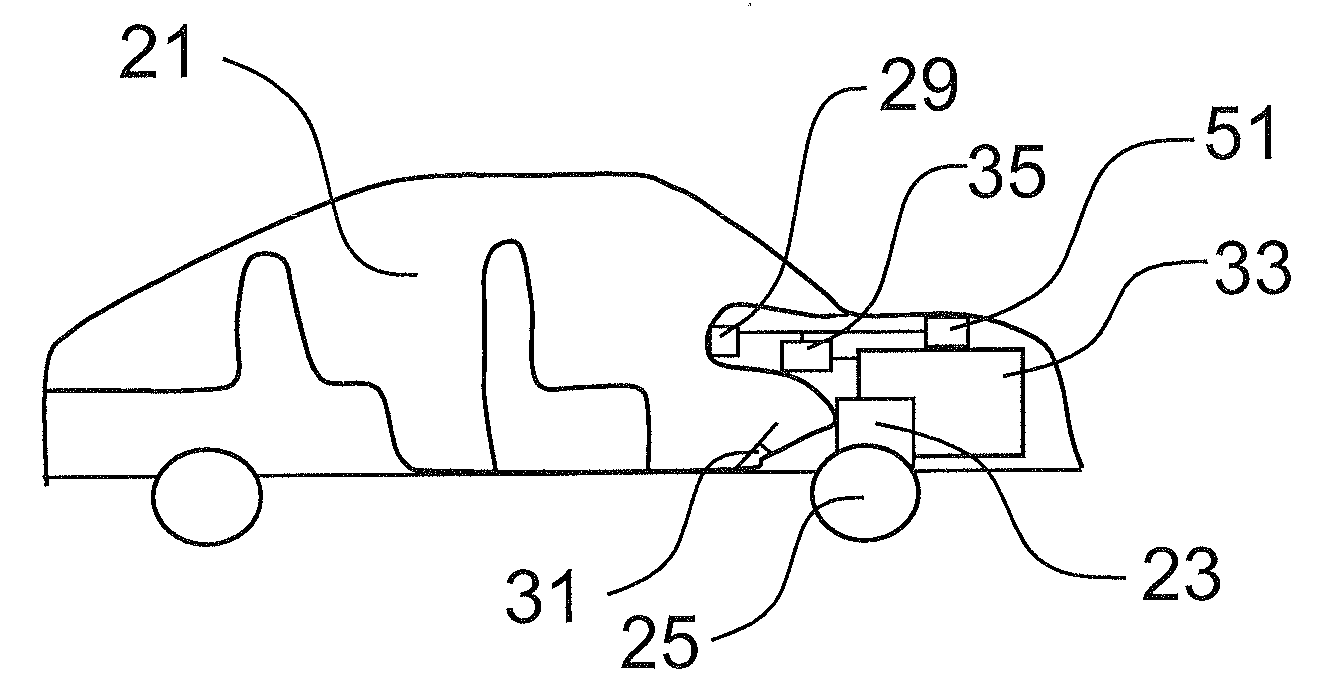
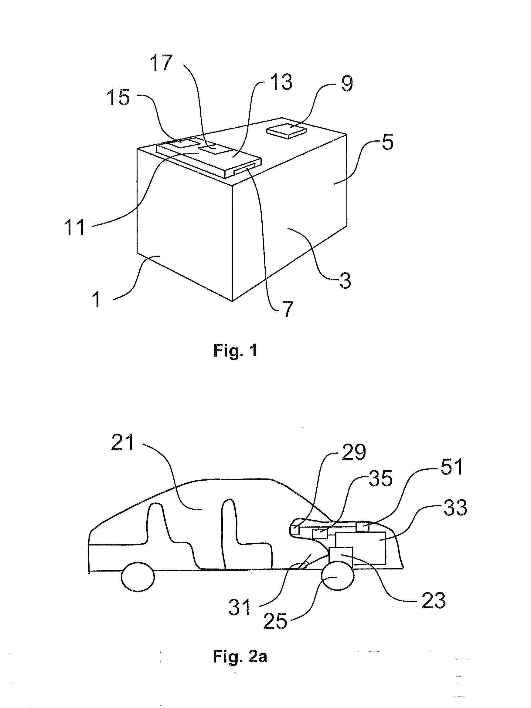
[0025]In FIG. 1 a battery pack 1 comprising at least one battery cell 3 is shown. The battery cell comprises a body 5 containing chemicals for storing electric energy and for generation of a voltage through chemical reaction. The battery cell 3 further comprises a first 7 and a second 9 battery pole for supplying the generated voltage to external circuits and ultimately to a load. The battery pack 1 further comprises a battery control circuit 11 connected with one pole of the battery cell, and arranged to be able to either feed, or avoid feeding, the voltage supplied by the battery cell 3 through the battery control circuit 11.

[0026]In this example the battery control circuit 11 comprises a semi-conductor device comprising a first connector 13 electrically connected with the first pole 7 of the battery cell, a second connector 15 arranged to supply the voltage to an external circuit including a load, and a switch control 17. The semi-conductor device is in this example a FET, or fie...


PUM


Abstract

A battery pack (33) includes at least one battery cell (39), and is designed to supply an output voltage for feeding electric energy to a load (23) so that the load may perform a function. A battery control device (35) arranged to generate control signals for controlling a battery pack, a device (21) including a battery pack, and a method for controlling a battery pack are also described.

Description

TECHNICAL FIELD[0001]The present invention relates to a battery pack, a battery control device for a battery pack, a device comprising a battery control device and a battery pack, and a method for controlling a battery pack.PRIOR ART[0002]Battery packs comprising one or more battery cells for providing energy to electric devices that are unsuited to be connected with a stationary power grid during their operation are known in the art. Examples of electrical devices powered by battery packs include electric vehicles, mobile phones, electric tools, work machines and others. Battery packs may also be used for grid balancing and other forms of energy storage. One problem with battery packs having many battery cells connected in series is that the voltage may be very high, so that the high voltage becomes a hazard to people or equipment, in particular in case of an emergency or a malfunction.[0003]One method of overcoming =this problem is shown in patent document U.S. Pat. No. 5,238,083,...

Claims


Application Information

Patent Timeline
Patent Type & Authority Applications(United States)
IPC IPC(8): H02J7/00H02P21/00
CPCB60L11/1851Y02T10/705Y02T10/7005B60L58/10Y02T10/70B60L50/60B60L3/04H02J7/0032
Inventor BERGFJORD, THOMAS
Owner HDD SERVO MOTORS
Why Eureka
Try Eureka