
Ultrasound diagnostic apparatus and ultrasound image producing method

a diagnostic apparatus and ultrasound technology, applied in diagnostics, ultrasonic/sonic/infrasonic data transmission, medical science, etc., can solve the problems of consuming a lot of time and difficult to switch the connection without interruption of operation, so as to reduce the possibility of the connection being switched and reduce the workflow

Active Publication Date: 2012-09-13
FUJIFILM CORP
View PDF2 Cites 10 Cited by
  • Summary
  • Abstract
  • Description
  • Claims
  • Application Information

AI Technical Summary

Benefits of technology

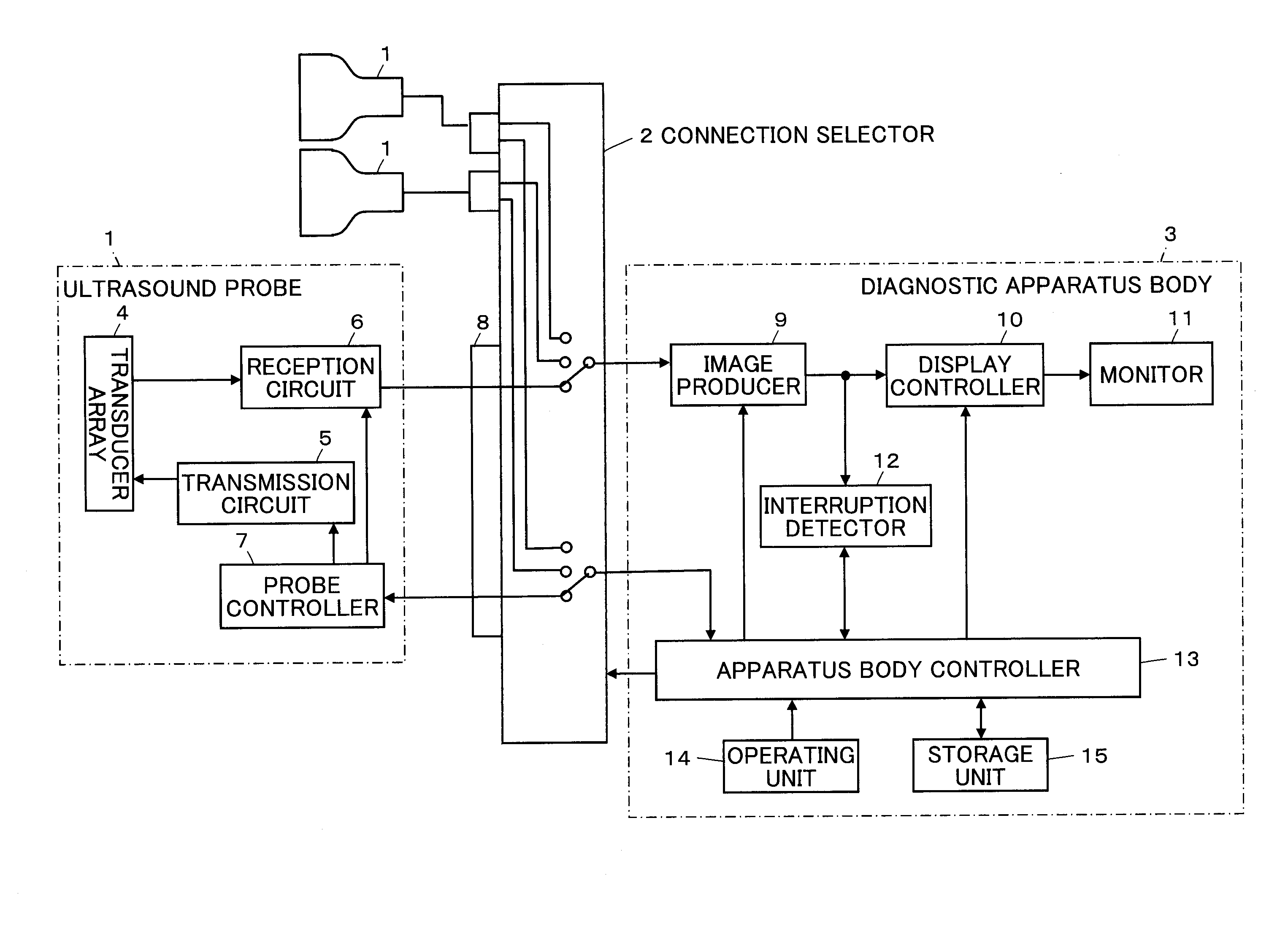
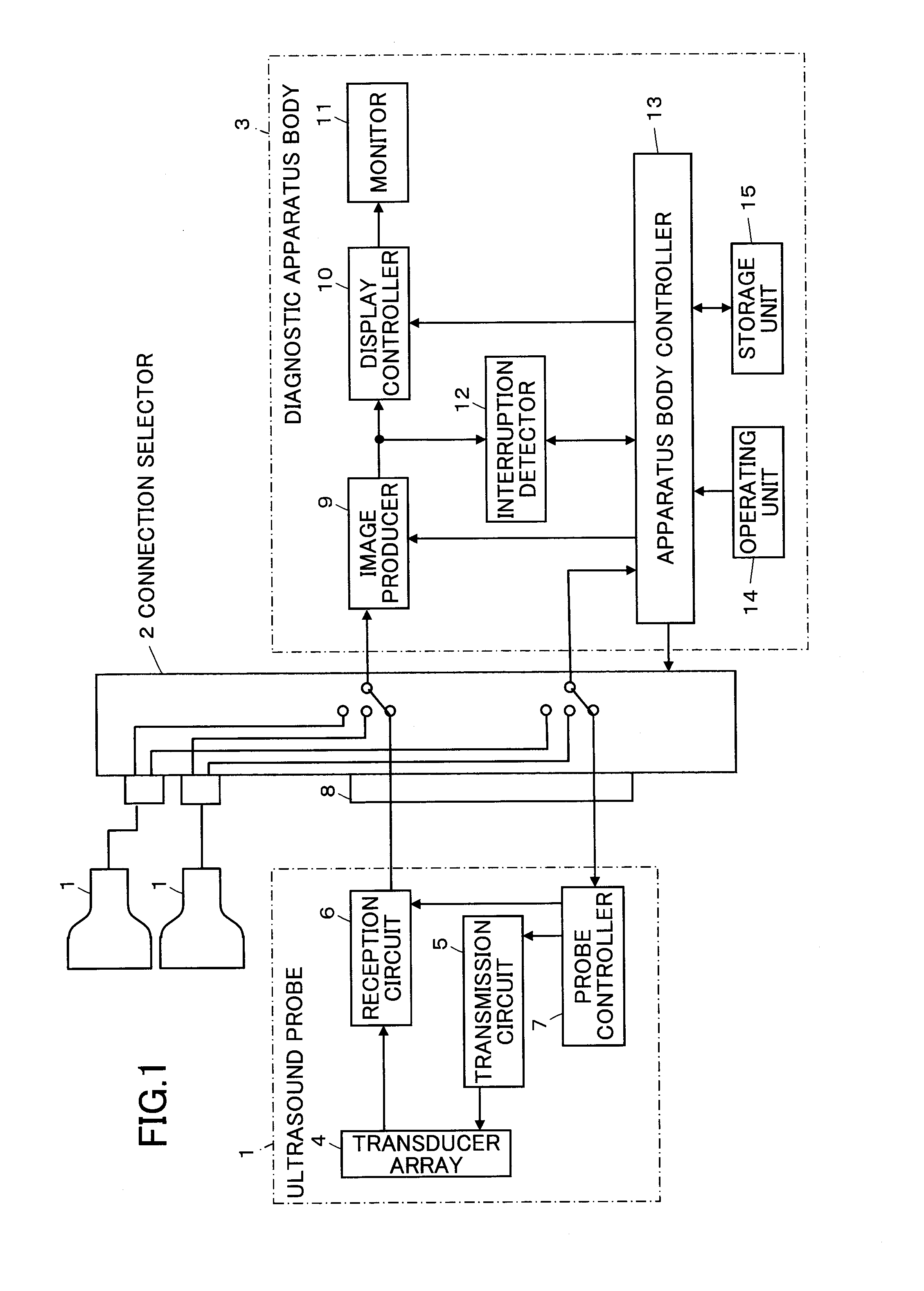
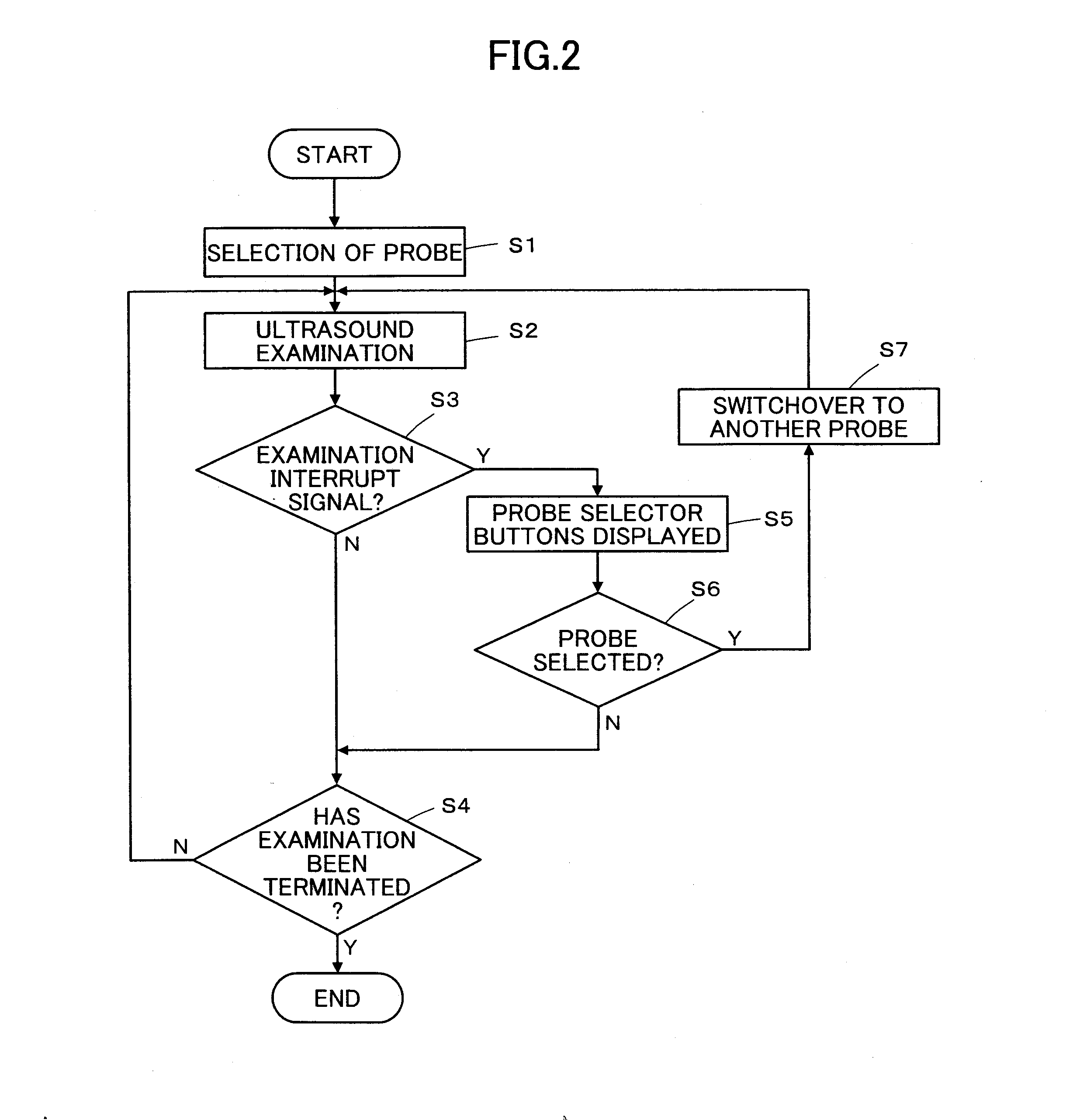
The present invention provides an ultrasound diagnostic apparatus and method that reduces the possibility of switching the connection between ultrasound probes and the apparatus body without the operator's intention, thus saving time and improving the efficiency of the ultrasound examination. The apparatus includes a connection selector for selectively switching the connection between the ultrasound probes and the apparatus body, an interruption detector for detecting interruption of ultrasound examination, and a controller for causing the apparatus body to display a selection screen for selecting one of the ultrasound probes to be subsequently used when interruption of ultrasound examination is detected. The technical effect of the invention is to improve the overall efficiency and accuracy of ultrasound examination.

Problems solved by technology

However, given automatic switching of the connection between the ultrasound probe and the apparatus body effected upon the detection by the sensor, there is a possibility of the connection being switched automatically as the sensor detects a touch not intended by the operator.
In general, to switch the connection between the ultrasound probes and the apparatus body, all the connections between the probes and the apparatus body need to be rewired, making switchover of the connection without interruption of the operation difficult, and hence consuming much time to switch the connection from one selected against the operator's intention to another.

Method used


Image

  • Ultrasound diagnostic apparatus and ultrasound image producing method
  • Ultrasound diagnostic apparatus and ultrasound image producing method
  • Ultrasound diagnostic apparatus and ultrasound image producing method

Examples


embodiment 2

[0064]FIG. 6 illustrates a configuration of an ultrasound probe 21 used in an ultrasound diagnostic apparatus according to Embodiment 2. The ultrasound probe 21 has the same components as the ultrasound probe 1 in Embodiment 1 illustrated in FIG. 1 except that a scan state detector 22 is provided and connected to the probe controller 7. The scan state detector 22 detects the scan state of the ultrasound probe 21 as operated by the operator and may be constituted, for example, by a gyro sensor that detects the movement of the ultrasound probe 21, a pressure sensor that detects the pressure with which the operator holds the ultrasound probe 21, or a temperature sensor that detects the body temperature of the operator touching the ultrasound probe 21.

[0065]The interrupt signal is produced by the interruption detector 12 as illustrated in FIG. 7 as in Embodiment 1; the B mode image is produced in step S11, and judgment is made in step S12 as to whether the B mode image contains an image...


PUM


Abstract

An ultrasound diagnostic apparatus includes a plurality ultrasound probes, an apparatus body for producing an ultrasound image based on the reception data obtained by one of the ultrasound probes, a connection selector for selectively switching a connection between the ultrasound probes and the apparatus body, an interruption detector for detecting interruption of ultrasound examination, and a controller for causing the apparatus body to display a selection screen for selecting one of the ultrasound probes to be subsequently used when the interruption detector detects interruption of ultrasound examination, wherein when an operator selects one of the ultrasound probes to be subsequently used from the displayed selection screen, the controller controls the connection selector to connect the selected ultrasound probe with the apparatus body.

Description

BACKGROUND OF THE INVENTION[0001]The present invention relates to an ultrasound diagnostic apparatus and an ultrasound image producing method and particularly to an ultrasound diagnostic apparatus wherein the connection between a diagnostic apparatus body and one of a plurality of ultrasound probes can be switched.[0002]Conventionally, ultrasound diagnostic apparatus using ultrasound images are employed in medicine. In general, this type of ultrasound diagnostic apparatus comprises an ultrasound probe having a built-in transducer array and an apparatus body connected to the ultrasound probe. The ultrasound probe transmits an ultrasonic beam toward the inside of a subject's body, receives ultrasonic echoes from the subject, and the apparatus body electrically processes the reception signals to produce an ultrasound image.[0003]This type of ultrasound diagnostic apparatus use different sorts of ultrasound probes depending on the diagnosis conditions to meet different diagnosis conditi...

Claims


Application Information

Patent Timeline
Patent Type & Authority Applications(United States)
IPC IPC(8): A61B8/14
CPCA61B8/4477A61B8/56A61B8/465
Inventor KOJIMA, TETSUYA
Owner FUJIFILM CORP
Learn More