Spinal implant device with fixation plates and lag screws and method of implanting

a technology of fixation plate and lag screw, which is applied in the field of spinal implant devices, can solve the problems of many devices that require special surgical tools, biomechanical weakened and hampered, and the fixation of the spinal process, and achieve the effect of superior spinous process and superior spinous process

Inactive Publication Date: 2012-09-13
MASSOUDI FARZAD
View PDF4 Cites 33 Cited by
  • Summary
  • Abstract
  • Description
  • Claims
  • Application Information

AI Technical Summary

Benefits of technology

[0011]According to various embodiments, the method further includes positioning the first fixation plate along the spinous processes with the first superior end adjacent the superior spinous process and the first inferior end adjacent the inferior spinous process. The method further includes positioning the second fixation plate along the spinous processes with the second superior end adjacent the superior spinous process and the second inferior end adjacent the inferior spinous process. The method further includes inserting a first lag screw through the first and third screw holes and superior spinous process. The method further includes threadedly engaging the first lag screw with a respective one of the first or third screw holes. The method further includes inserting a second lag screw through the second and fourth screw holes and inferior spinous process. The

Problems solved by technology

Spinous process fixation, since its emergence, has been biomechanically weakened and hampered by the method of spinous process fixation w

Method used


Image

  • Spinal implant device with fixation plates and lag screws and method of implanting
  • Spinal implant device with fixation plates and lag screws and method of implanting
  • Spinal implant device with fixation plates and lag screws and method of implanting

Examples


Embodiment Construction

[0027]The detailed description set forth below in connection with the appended drawings is intended as a description of certain embodiments of the present disclosure, and is not intended to represent the only forms that may be developed or utilized. The description sets forth the various functions in connection with the illustrated embodiments, but it is to be understood, however, that the same or equivalent functions may be accomplished by different embodiments that are also intended to be encompassed within the scope of the present disclosure. It is further understood that the use of relational terms such as top and bottom, first and second, and the like are used solely to distinguish one entity from another without necessarily requiring or implying any actual such relationship or order between such entities.

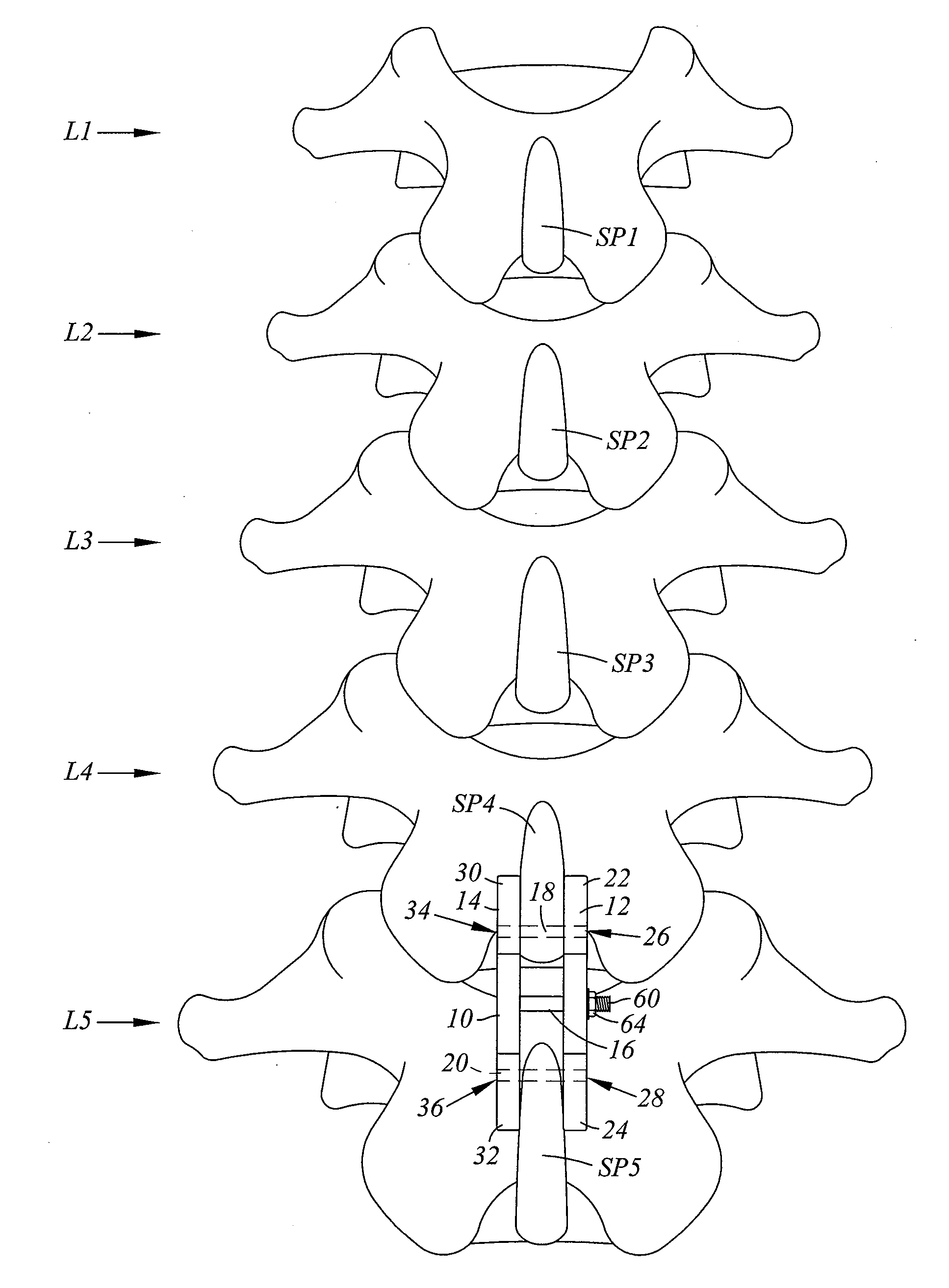
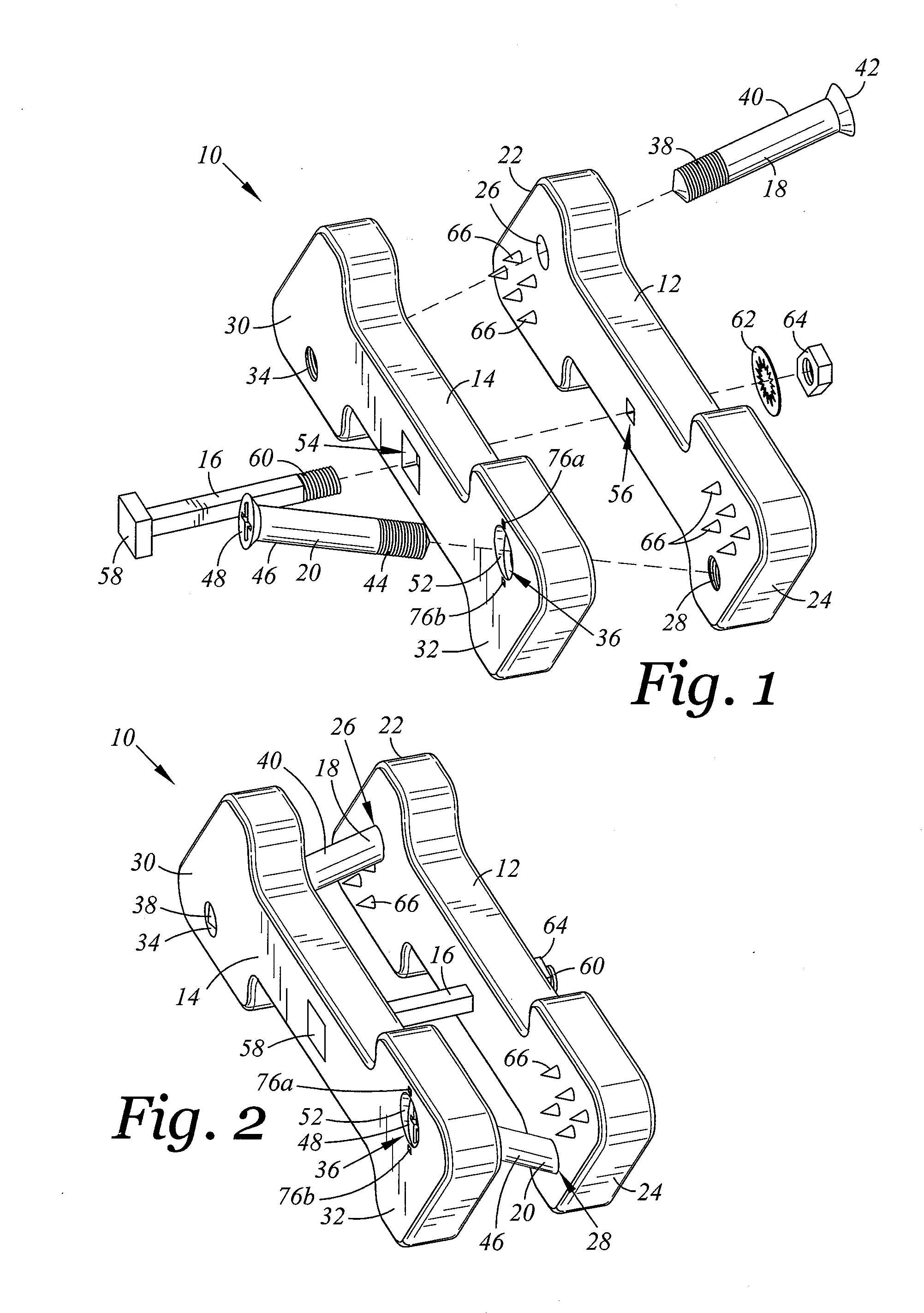
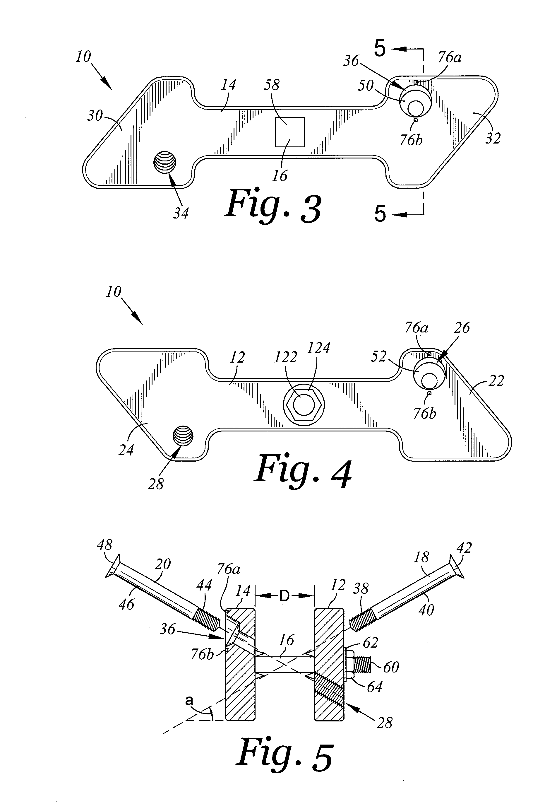
[0028]Referring now to FIG. 1, there is depicted an exploded perspective view of a spinal implant device 10 according to an embodiment of the invention. FIG. 2 is the spinal i...


PUM


Abstract

There is provided a spinal implant device for placement between adjacent spinous processes. The spinal implant device includes first and second fixation plates, a connector, and first and second lag screws. The first fixation plate includes a first and second screw holes. The second fixation plate includes third and fourth screw holes. The first lag screw extends through the first and third screw holes and threadedly engages a respective one of the first or third screw holes with the superior spinous process disposed between the first and second superior ends. The second lag screw extends through the second and fourth screw holes and threadedly engages a respective one of the second or fourth screw holes with the inferior spinous process disposed between the first and second inferior ends. A method of implanting the device is provided.

Description

CROSS-REFERENCE TO RELATED APPLICATIONS[0001]The present patent application is related to U.S. patent Ser. No. 13 / 033,450 filed on Feb. 23, 2011, entitled SPINAL IMPLANT DEVICE WITH FUSION CAGE AND FIXATION PLATES AND METHOD OF IMPLANTING.STATEMENT RE: FEDERALLY SPONSORED RESEARCH / DEVELOPMENT[0002]Not ApplicableBACKGROUND[0003]1. Technical Field[0004]The present disclosure relates generally to spinal implant devices. More particularly, the present disclosure relates to spinal implant devices with fixation plates and lag screws, and methods of implanting the same.[0005]2. Related Art[0006]There have been a myriad of spinal implant devices and techniques for treating spinal conditions that focus on fusion of the various levels of the spine. Moreover, a myriad of fixation devices and techniques have been implemented. Such fixation techniques range from use of peticle or facet screws with attached connecting rods to interspinous devices interacting with the spinous processes (such as sp...

Claims


Application Information

Patent Timeline
IPC IPC(8): A61B17/70A61B17/88
CPCA61B17/7068A61B17/683A61B17/1757A61B17/1728A61B17/7067
Inventor MASSOUDI, FARZAD
Owner MASSOUDI FARZAD
Why Eureka
Try Eureka