Door closer
- Summary
- Abstract
- Description
- Claims
- Application Information
AI Technical Summary
Benefits of technology
Problems solved by technology
Method used
Image
Examples
first embodiment
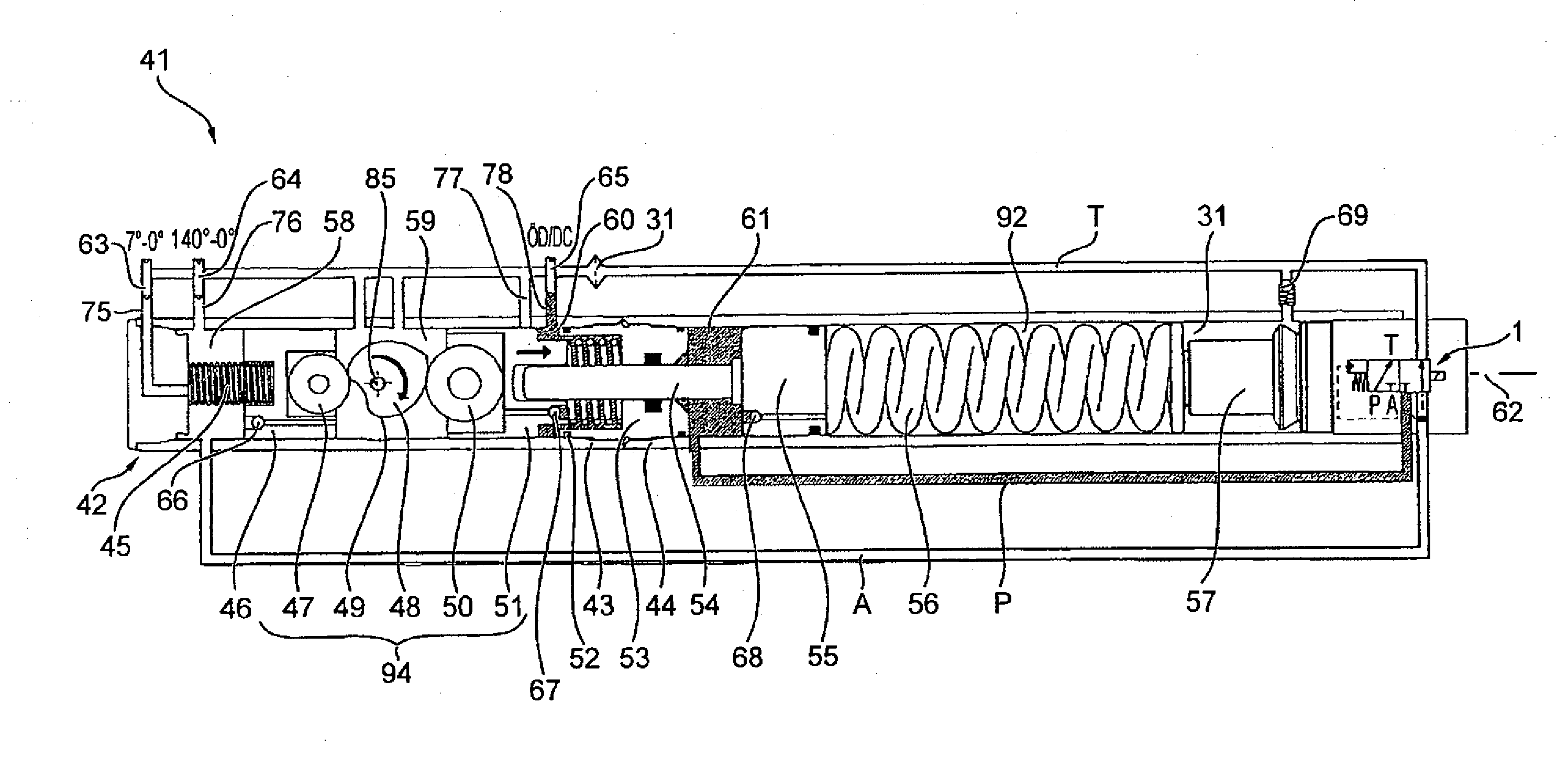
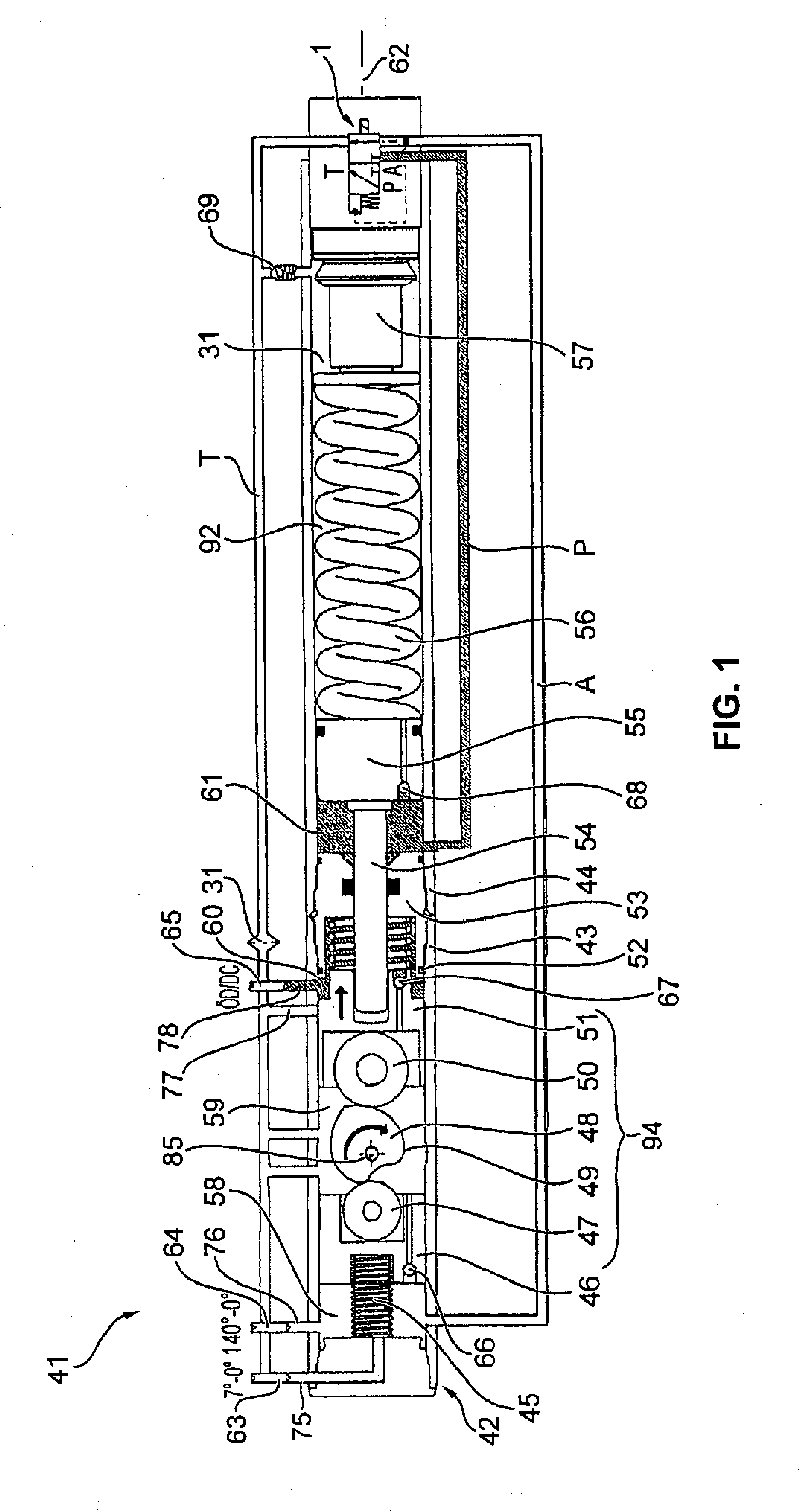
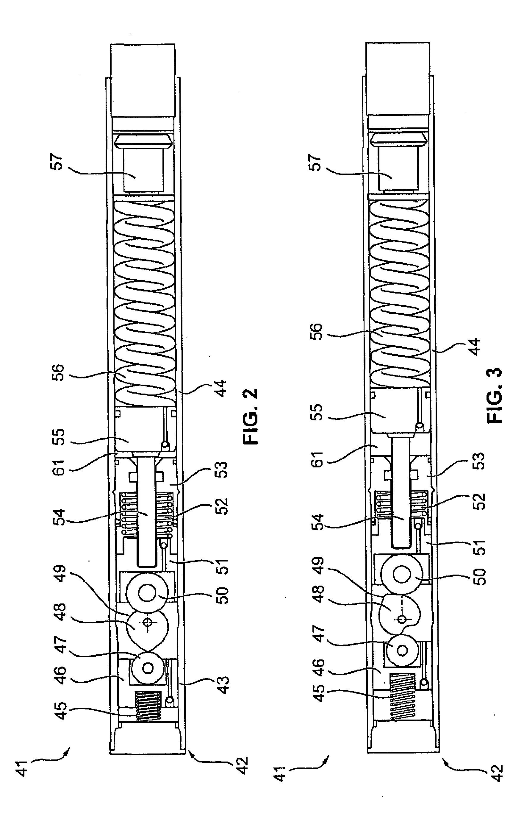
[0086]In the following, the basic structure as well as the hydraulic control and the function of a door closer 41 is explained with reference to FIG. 1.
[0087]The door closer 41 extends along a longitudinal door closer axis 62. The door closer 41 comprises a door closer housing 42 that in turn consists of a first door closer housing part 43 and a second door closer housing part 44. In FIG. 1, the various hydraulic lines are shown to be outside the door closer housing 42. This illustration, however, is only given for facilitating inspection. In practice, the hydraulic lines are integrated into the door closer housing 42. In the following, the structure of the door closer 41 along its longitudinal door closer axis 62 is explained from left to right. A first pressure spring 45 is supported against the door closer housing 42, in particular against a front face of the first door closer housing part 43. The first pressure spring 45 pushes a piston assembly 94. This piston assembly 94 is g...
second embodiment
[0096]FIGS. 7 and 8 show a door closer 41 according to a Identical components or components identical in function are designated with identical reference numerals in all embodiments. FIG. 7 shows a door closer 41 during biasing of the closer spring 56. In FIG. 8, the lock compartment 61 is hydraulically blocked through the pressure line P. Consequently, the closer spring tension piston 55 and the closer spring 56 remain in their tensed positions. The piston assembly 94 and the door are freely swingable.
[0097]Apart from the difference described in the following, the second embodiment corresponds to the first embodiment: Contrary to the first embodiment, an additional piston 95 is arranged between the separating wall 53 and the piston assembly 94, in particular the opening piston 51, in the second embodiment. The additional piston 95 is fixedly connected to the piston rod 54 for transmitting a translational motion. The first front face 74 is formed frontally at the additional piston ...
third embodiment
[0099]The piston assembly 94 proposed in FIGS. 9 and 10 replaces the piston assembly 94 of FIGS. 1 to 7, in particular the damper piston 46 including the first cam disc 47 and the opening piston 51 including the second cam disc 50. The output shaft 48 remains unchanged. Due to the use of the piston assembly 94 the first pressure spring 45 and the second pressure spring 52 are not longer required, however, can be used in addition.
[0100]FIG. 9 shows the piston assembly 94, wherein the damper piston 46 and the opening piston 51 are connected by a first tie rod 81, a second tie rod 82, a third tie rod 83, and a forth tie rod 84. The four tie rods 81 to 84 are arranged in parallel with the longitudinal door closer axis 62. In addition, the four tie rods 81 to 84 are arranged at four corners of a square or rectangle to be considered for the purpose of explanation only. The output axis 85 of the output shaft 48 passes through the section point of the diagonals of said square or rectangle....
PUM
 Abstract
Description
Claims
Application Information
 - R&D
- Intellectual Property
- Life Sciences
- Materials
- Tech Scout
- Unparalleled Data Quality
- Higher Quality Content
- 60% Fewer Hallucinations
Browse by: Latest US Patents, China's latest patents, Technical Efficacy Thesaurus, Application Domain, Technology Topic, Popular Technical Reports.
© 2025 PatSnap. All rights reserved.Legal|Privacy policy|Modern Slavery Act Transparency Statement|Sitemap|About US| Contact US: help@patsnap.com


