Multi-function machines, hydraulic systems therefor, and methods for their operation

a multi-functional machine and hydraulic system technology, applied in the direction of fluid couplings, rotary clutches, servomotors, etc., can solve the problems of wasting energy and throttling the flow through the control valve, and achieve the effect of reducing the engine power, energy and fuel consumption requirements of such machines

Inactive Publication Date: 2012-09-20
PURDUE RES FOUND INC
View PDF1 Cites 35 Cited by
  • Summary
  • Abstract
  • Description
  • Claims
  • Application Information

AI Technical Summary

Benefits of technology

[0010]A technical effect of the invention is the ability of a hydraulic system to capture energy from actuators or an engine of a machine, store the captured energy in an energy storage device, and then deliver the captured energy to the engine / actuators in a controlled manner and time frame. The invention is particularly adapted for use with architectural arrangements of both rotary and linear actuators that are used to control implements of a machine, and offers the possibility of significantly reducing the engine power, energy, and fuel consumption requirements of such machines.
[0011]Other aspects and advantages of this invention will be better appreciated from the following detailed description.

Problems solved by technology

However, throttling flow through control valves is known to waste energy.

Method used


Image

  • Multi-function machines, hydraulic systems therefor, and methods for their operation
  • Multi-function machines, hydraulic systems therefor, and methods for their operation
  • Multi-function machines, hydraulic systems therefor, and methods for their operation

Examples


second embodiment

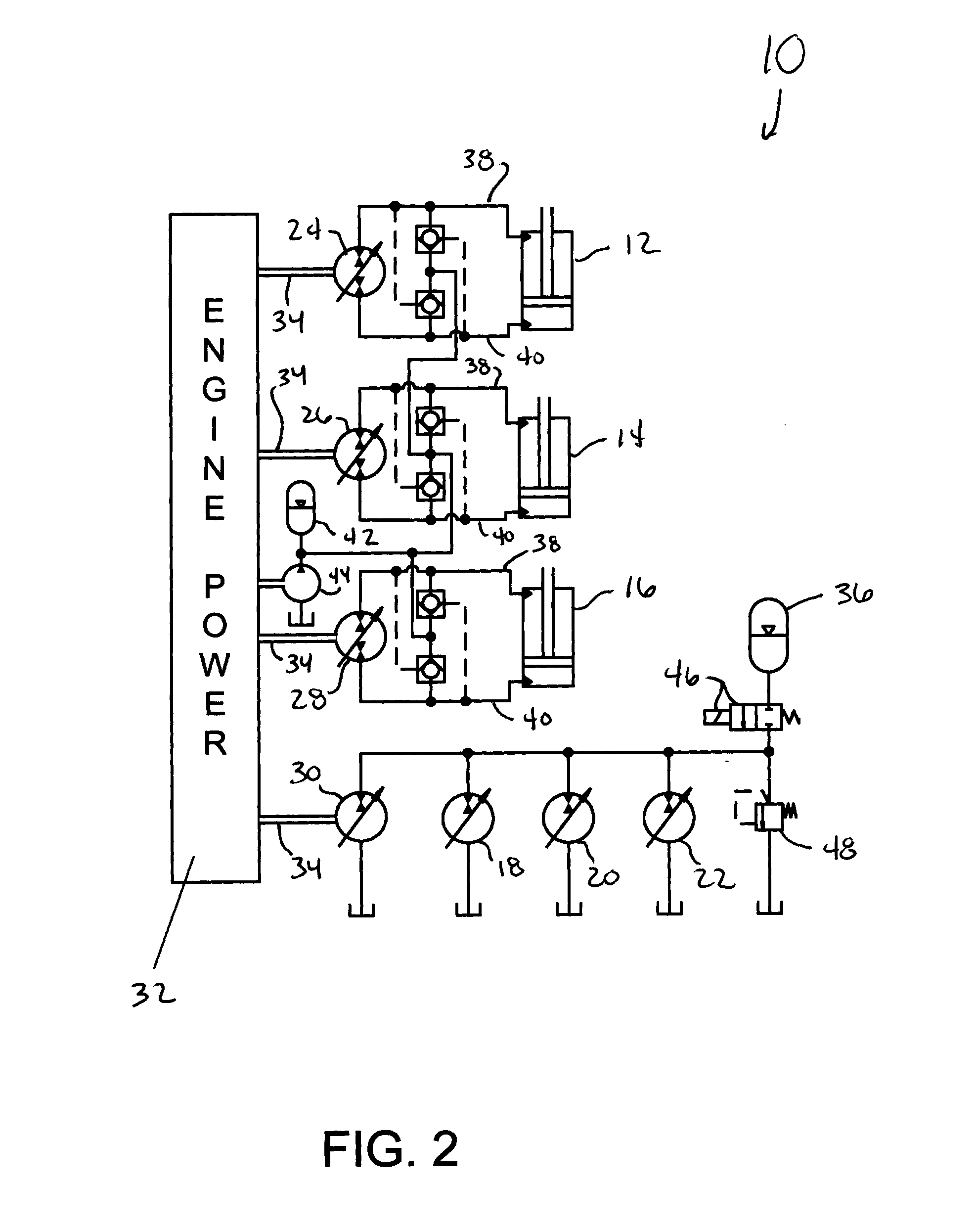
[0023]FIG. 3 represents a hybrid displacement-controlled hydraulic system 10 of the invention that is similar to FIG. 2, but differs from the embodiment of FIG. 2 as a result of the secondary control of the rotary actuators 18, 20 and 22 being within a closed circuit, as opposed to each rotary actuator 18, 20 and 22 being connected to a reservoir as represented in FIG. 2. FIG. 3 shows the closed circuit as also being connected to the low pressure accumulator 42, which ensures that a continuous supply of hydraulic fluid is available to each rotary actuator 18, 20 and 22. As such, the linear actuators 12, 14 and 16 and the rotary actuators 18, 20 and 22 are both mechanically and fluidically interconnected through their mechanical connections 34 to the engine 32 and through the fluid lines to the low pressure accumulator 42, such that the hydraulic circuits containing the linear actuators 12, 14 and 16 and rotary actuators 18, 20 and 22 contain the same hydraulic fluid. However, it sho...

third embodiment

[0024]FIGS. 4 and 5 represent a hybrid displacement-controlled hydraulic system 10 of the invention that is similar to FIG. 2, but differs by showing that the high pressure available from the high pressure accumulator 36 can be used as inputs to controls 50 for each of the variable displacement pump / motors 24, 26 and 28 for the linear actuators 12, 14 and 16 and for the energy storage pump 30 and each rotary actuator 18, 20 and 22. In particular, FIG. 5 represents an example of one of the controls 50 for the pump / motors 24, 26 and 28. The control 50 includes a line-in 52 from the high pressure accumulator 36 and an electronically-controlled hydraulic valve 54 that controls the flow of hydraulic fluid from the line-in 52 to a hydraulic cylinder 56, whose output (position) is used to control the pump / motor 24 / 26 / 28 as schematically represented in FIG. 5. This additional capability is beneficial because the high pressure of the accumulator 36 is available within the system 10 at no ext...

fourth embodiment

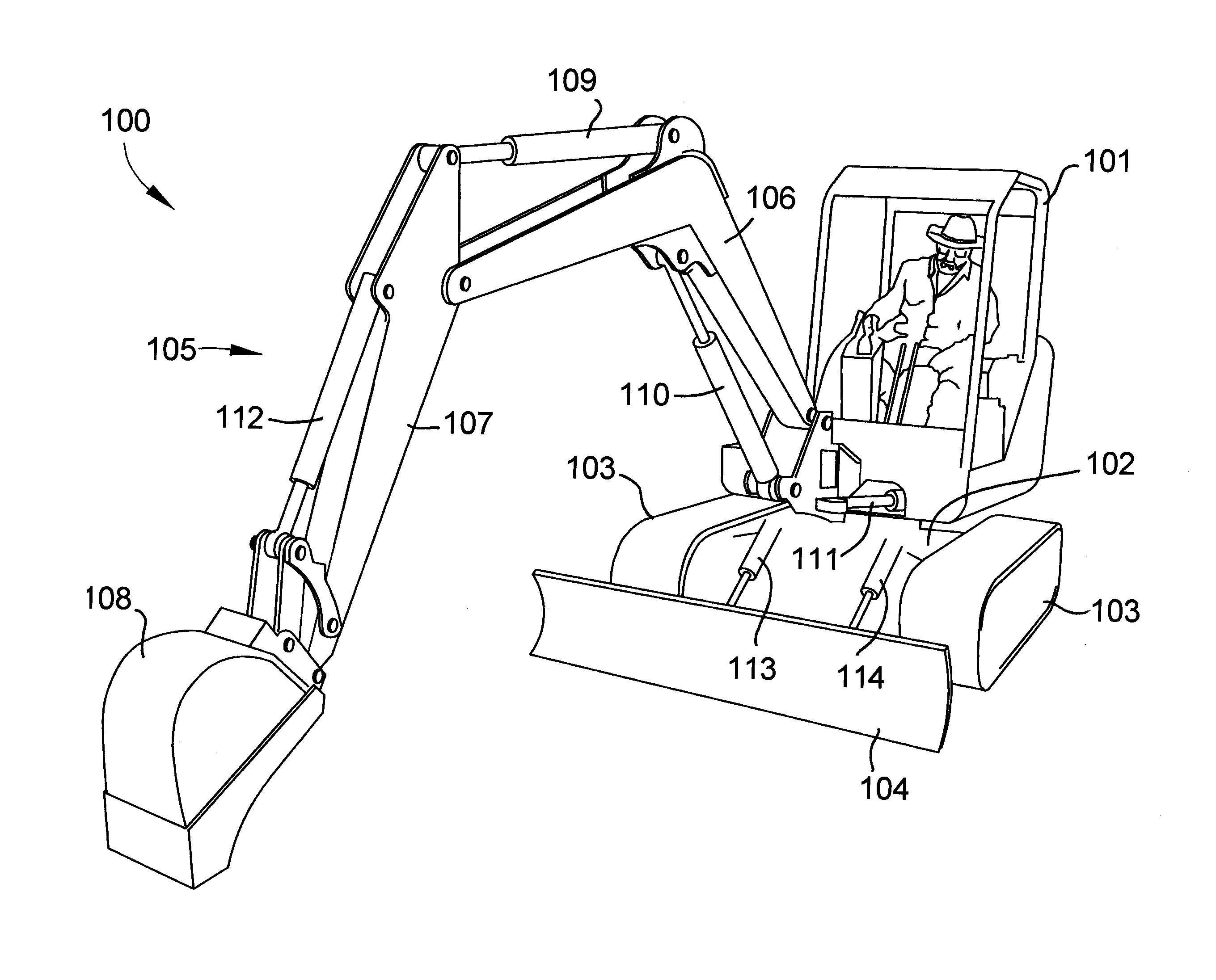
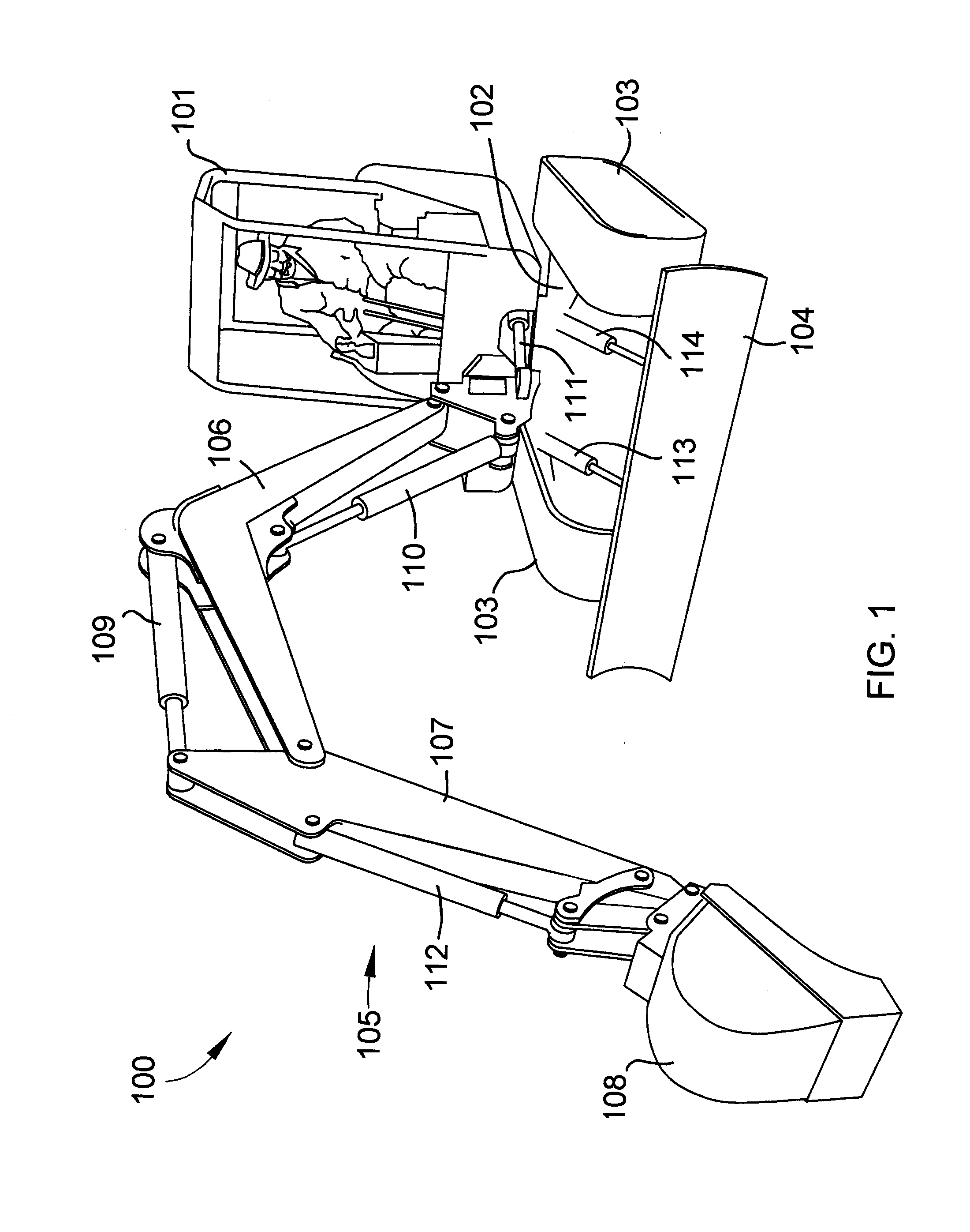
[0025]FIG. 6 represents a hybrid displacement-controlled hydraulic system 10 of the invention that is similar to FIG. 2, but differs from the embodiment of FIG. 2 as a result of the inclusion of an auxiliary attachment 58 that is fluidically connected to the energy storage pump 30, rotary actuators 18, 20 and 22, and high pressure accumulator 36 through an electronically-controlled hydraulic valve 59. FIG. 6 is notable for illustrating an additional benefit of the system 10, particularly in relation to conventional displacement control systems, for example, of the type conventional used to control the rotary functions (rotary hydraulic drive motors for the tracks and rotary hydraulic swing motor for the cabin) of excavators of the type represented in FIG. 1. Perhaps the largest disadvantage of conventional displacement control systems is their requirement for one pump for each actuator. For an excavator of the type shown in FIG. 1, such a requirement conventionally necessitates the ...


PUM


Abstract

Systems and methods for controlling and actuating actuators that perform multiple functions in a machine. Such systems and methods encompass a hydraulic system adapted to control and actuate the actuators of the machine. The hydraulic system includes variable displacement pump / motors connected to the engine in parallel. A first of the pump / motors controls a first of the actuators, and a second of the pump / motors is adapted to draw power from and deliver power to the engine and the first actuator, as well as control at least a second of the actuators. An energy storage device is connected in series with the second pump / motor and the second actuator, and accumulates a fluid pumped thereto by the second pump / motor, as well as delivers the fluid to the second pump / motor, depending on whether the second pump / motor delivers is delivering or drawing power from the engine or first actuators.

Description

CROSS REFERENCE TO RELATED APPLICATIONS[0001]This application claims the benefit of U.S. Provisional Application No. 61 / 453,368, filed Mar. 16, 2011, the contents of which are incorporated herein by reference.BACKGROUND OF THE INVENTION[0002]The present invention generally relates to systems for operating hydraulic circuits. More particularly, this invention relates to hydraulic systems containing multiple displacement-controlled (DC) actuators, for example, of a multi-function machine, and an energy storage system therefor.[0003]Compact excavators, wheel loaders and skid-steer loaders are examples of multi-function machines whose operations involve controlling movements of various implements of the machines. FIG. 1 illustrates a compact excavator 100 as having a cab 101 mounted on an undercarriage 102 via a swing bearing (not shown) or other suitable device. The undercarriage 102 includes tracks 103 and associated drive components, such as drive sprockets, rollers, idlers, etc. The...

Claims


Application Information

Patent Timeline
Patent Type & Authority Applications(United States)
IPC IPC(8): F15B1/02
CPCF15B1/024F15B11/17
Inventor IVANTYSYNOVA, MONIKA MARIANNEZIMMERMAN, JOSHUA DAVID
Owner PURDUE RES FOUND INC
Why Eureka
Try Eureka