
Automatic tire inflation system

a tire inflation system and tire inflation technology, applied in the direction of tire measurement, vehicle components, transportation and packaging, etc., can solve the problems of reduced gas mileage, prone to breakdown, and inability to handle fast turns well

Inactive Publication Date: 2012-09-20
NARLOCH ANDREW JOSEPH +1
View PDF0 Cites 65 Cited by
  • Summary
  • Abstract
  • Description
  • Claims
  • Application Information

AI Technical Summary

Benefits of technology

"The invention is an automatic tire inflation system that can be attached to a standard vehicle tire. The system senses tire pressure and, if too low, provides pressurized air from an air pump until the correct pressure is reached. The system also transmits tire pressure information to the driver inside the vehicle. The system is water resistant and vibration resistant, and it does not affect the balance of the tire. The system includes a battery powered air pump, an air pump electrical cable, a pneumatic stem connector, a pressure sensor switch, a pressure sensor switch electrical cable, a rechargeable battery power supply, a recharging jack, a waterproof jack cover, a battery cable, a motion sensor switch, a water resistant air filter, a counter weight, a water resistant hollow housing, a plurality of rim retaining fingers, and a printed circuit board. The system can be installed on a tire and is designed to automatically inflate the tire to the correct pressure."

Problems solved by technology

If pressure is too low, the vehicle may not handle fast turns well.
Additionally, low air pressure results in reduced gas mileage.
These designs rely on mechanisms located both inside the tire and outside the tire that, when put to practice, would be expensive and prone to breakdown due to the extreme temperature and vibration conditions that most tires go through during use.
However, there are deficiencies in the Loewe design.
This means that the wheel cover must be custom designed for each type of tire and vehicle and therefore is not easy to retrofit onto an existing vehicle.
However, a centrifugal intake valve is a costly way to detect motion and a possible way to incur air leakage problems.
Third, no provision is made to equalize the weight of the components to prevent wheel imbalance.
Fourth, no provision is made to be able to recharge the batteries located inside the wheel cover, meaning that the user would have to open the housing each time the batteries needed to be changed.

Method used


Image

  • Automatic tire inflation system
  • Automatic tire inflation system
  • Automatic tire inflation system

Examples


Embodiment Construction

[0026]Detailed descriptions of the preferred embodiment are provided herein. It is to be understood, however, that the present invention may be embodied in various forms. Therefore, specific details disclosed herein are not to be interpreted as limiting, but rather as a basis for the claims and as a representative basis for teaching one skilled in the art to employ the present invention in virtually any appropriately detailed system, structure or manner.

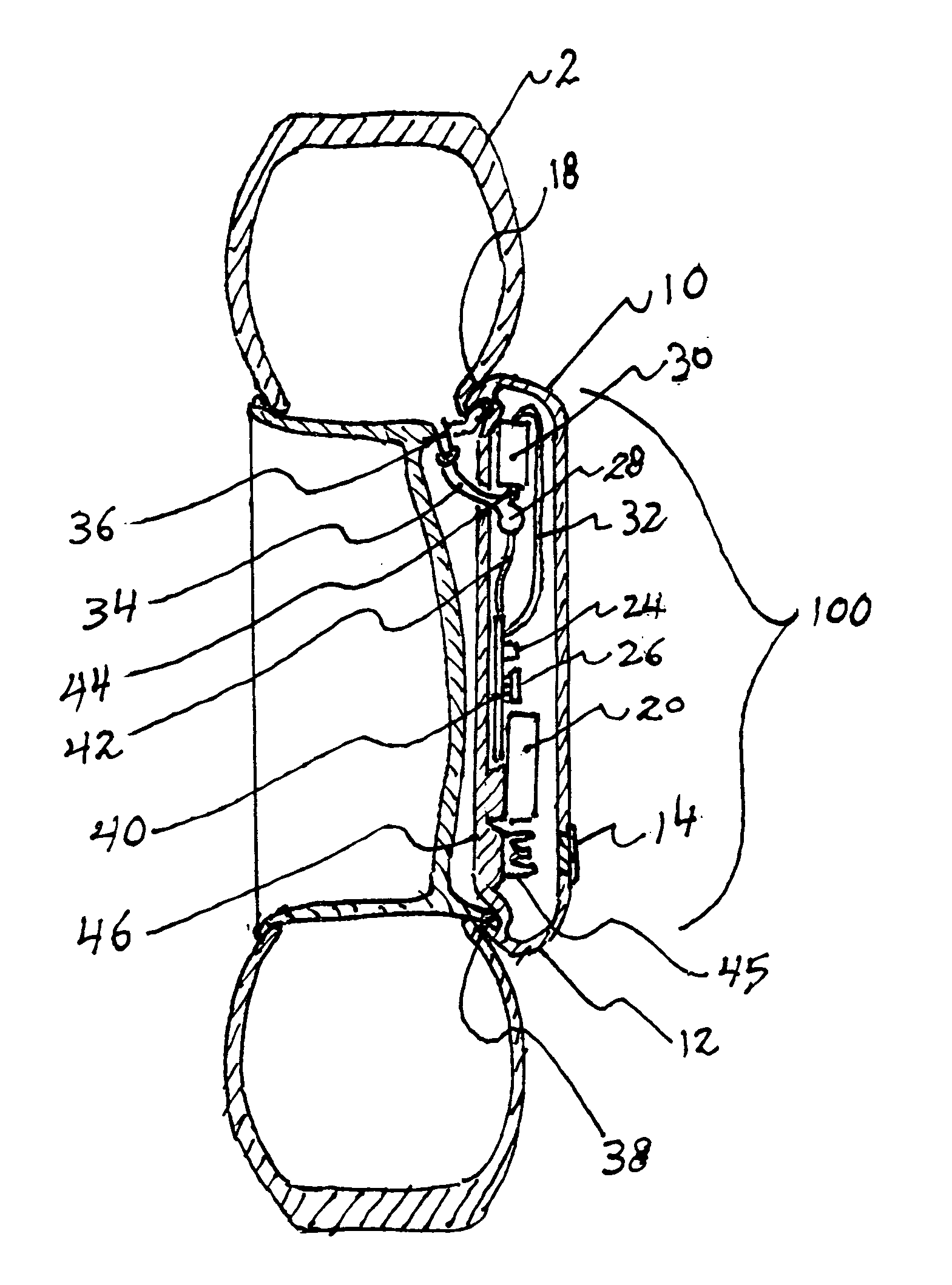
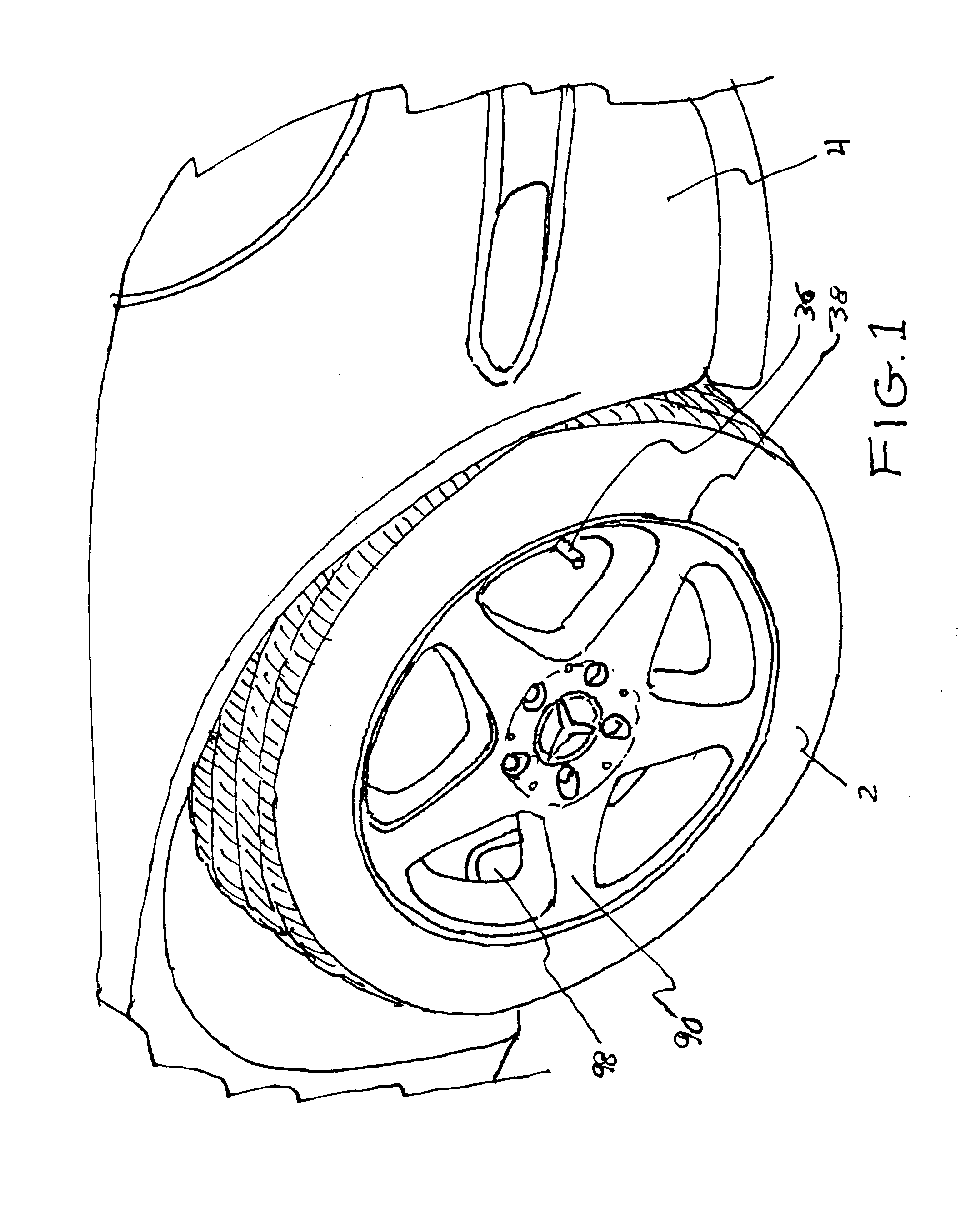
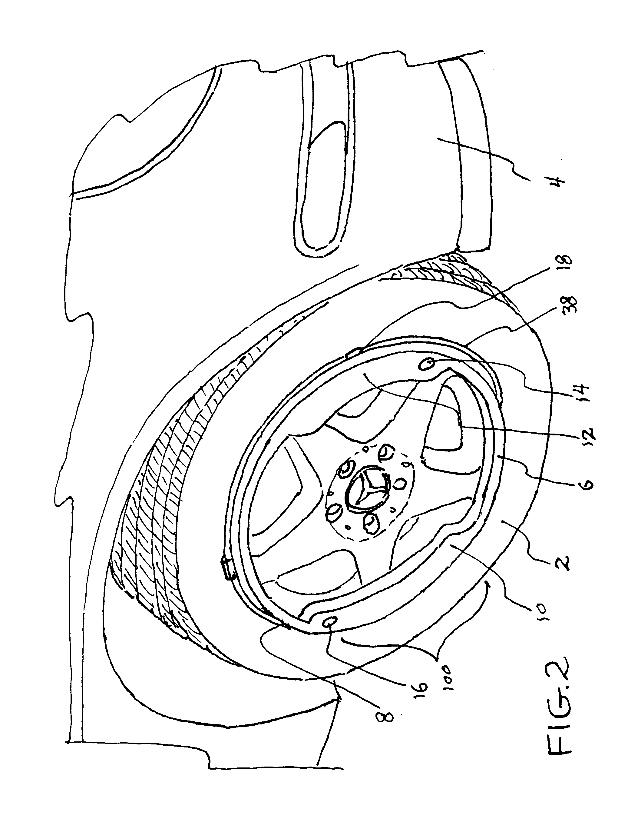
[0027]Referring now to FIG. 1 we see a standard tire 2 attached in a standard way to a vehicle 4. A standard rim 36 and rim support structure 90 can be seen as well as a standard air input valve 36 and brake mechanism 98. FIG. 2 shows the same tire 2 with the present invention 100 attached to the rim 38 via rim retaining fingers 18. The housing of the invention is comprised of two major portions 10, 12 connected by two hollow track portions 6, 8. Major portion 10 holds an air pump 30 and pressure sensor 28. Major portion 12 holds a b...


PUM


Abstract

An automatic tire inflation system including an air pump, a pressure sensor, a microprocessor and a rechargeable battery power supply all housed in a water resistant housing. The housing conforms to the diameter of the rim of a standard vehicle tire and is held to the tire by rim retaining fingers. A recharging jack is mounted inside the housing and is accessed through an aperture on the housing which is sealed by a removable waterproof cover. The microprocessor monitors air tire pressure being sent from the pressure sensor and activates the air pump when the pressure is determined to be too low by the microprocessor. The air pump turns off when the air tire pressure reaches a predetermined set point. The rechargeable battery is recharged by a standard charging device attached by a plug to the recharging jack. Similar automatic tire inflation systems can be mounted to each tire of the vehicle.

Description

CROSS REFERENCE TO RELATED APPLICATIONS[0001]Not ApplicableSTATEMENT REGARDING FEDERALLY SPONSORED RESEARCH OR DEVELOPMENT[0002]Not ApplicableDESCRIPTION OF ATTACHED APPENDIX[0003]Not ApplicableBACKGROUND OF THE INVENTION[0004]This invention relates generally to the field of automotive accessories and more specifically to an automatic tire inflation system.[0005]Pneumatic vehicle tires must be kept at a recommended pressure in order to perform optimally. If pressure is too low, the vehicle may not handle fast turns well. Additionally, low air pressure results in reduced gas mileage. It is therefore recommended that a person maintain optimal tire pressure at all times while driving. However, many drivers do not take the time to read tire pressure of each tire and add air as needed.[0006]It would therefore be an advantage to automatically pressurize the tire as needed to keep it at its ideal inflation pressure. A number of inventors have addressed this problem. Some of them have propo...

Claims


Application Information

Patent Timeline
Patent Type & Authority Applications(United States)
IPC IPC(8): B60C23/10
CPCB60C23/10B60C23/004
Inventor NARLOCH, ANDREW JOSEPHNARLOCH, JOSEPH ANDREW
Owner NARLOCH ANDREW JOSEPH
Learn More