

Pneumatic tire
a technology of pneumatic tires and pneumatic cylinders, which is applied in the field of pneumatic tires, can solve the problems such as the difficult to obtain the hoop effect of the belt, and achieve the effects of preventing the occurrence of delamination at the belt edge, reducing the difficulty of hoop effect, and effectively suppressing the outer diameter of the bel
- Summary
- Abstract
- Description
- Claims
- Application Information
AI Technical Summary
Benefits of technology
Problems solved by technology
Method used
Image

Examples
first embodiment
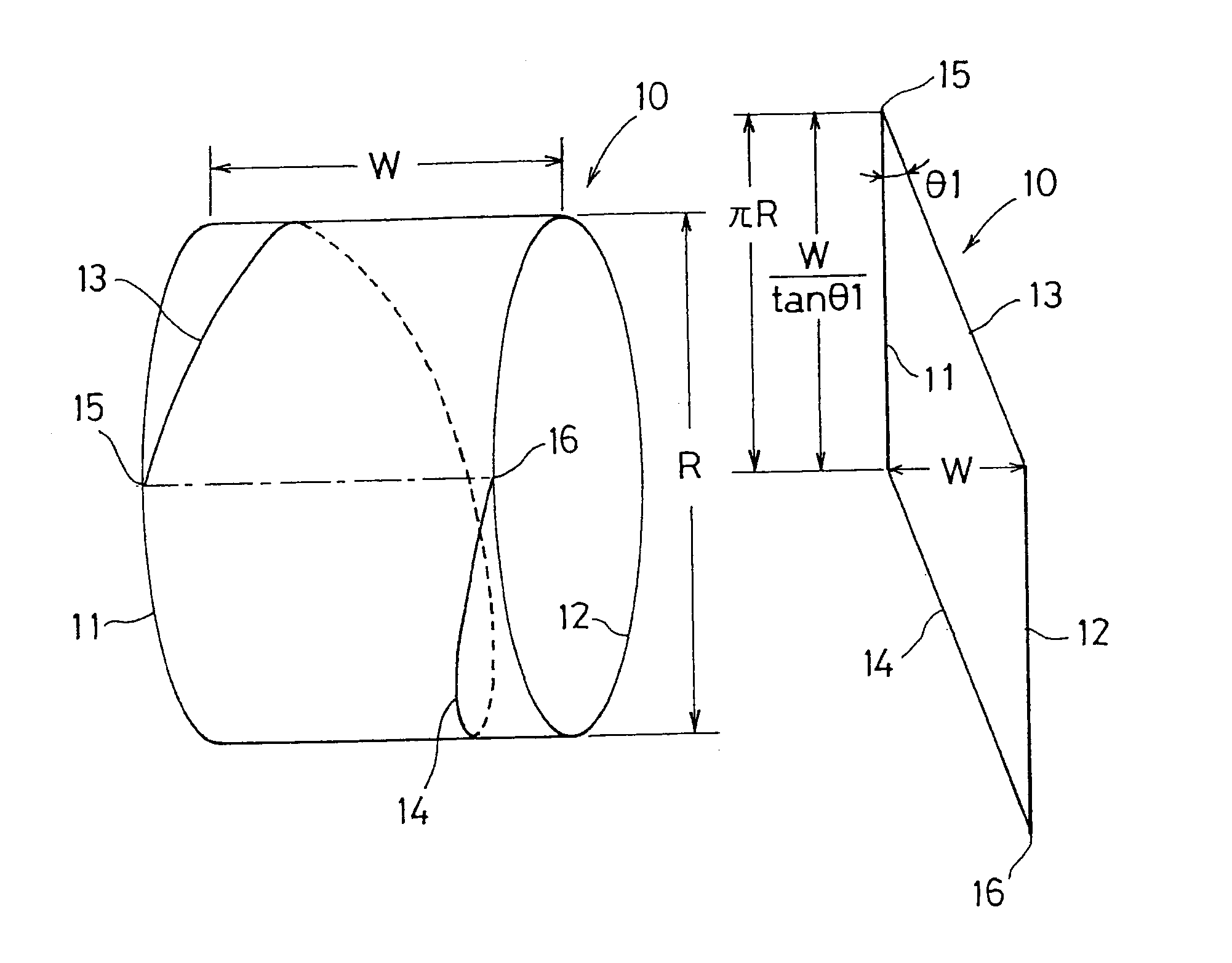
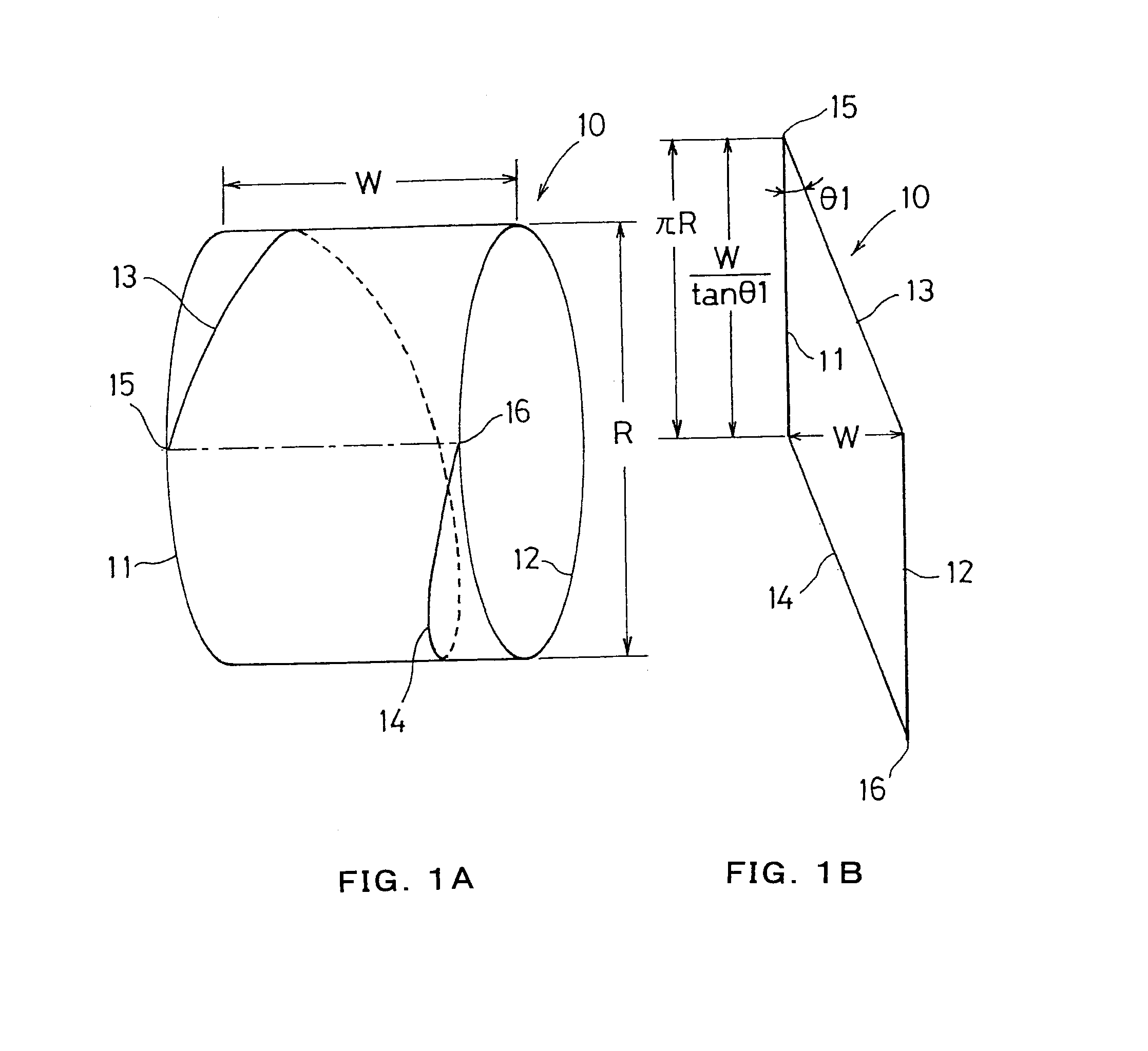
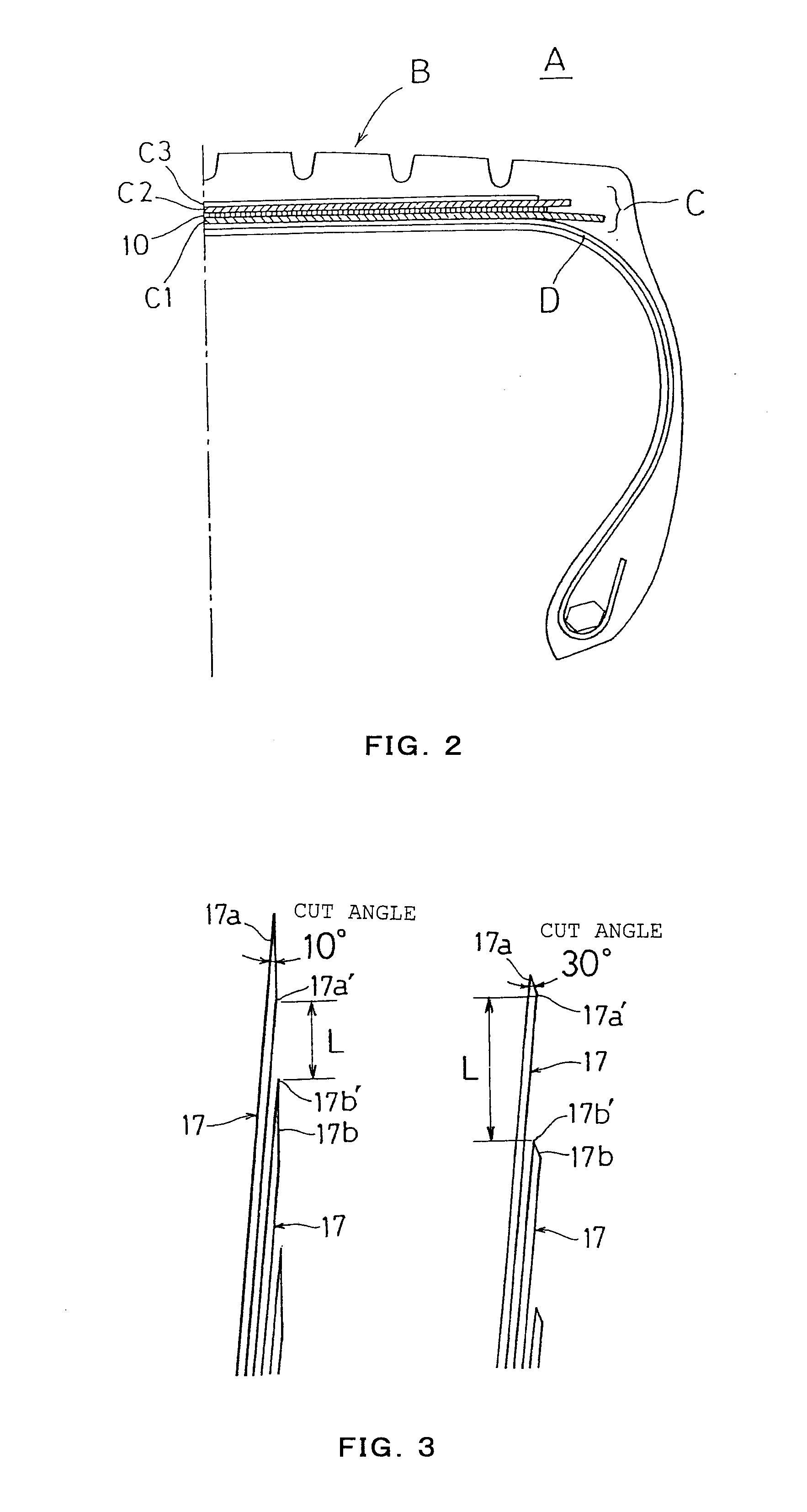
[0023]FIG. 1A shows a state that a parallelogram reinforcing belt 10 shown in FIG. 1B is cylindrically wound. In FIGS. 1A and 1B, W shows a width of a reinforcing belt, R shows a diameter of a reinforcing belt, 10 shows a reinforcing belt, 11 and 12 show circumferential direction sides of the reinforcing belt 10, 13 and 14 show inclined sides of the reinforcing belt 10, 15 shows an upper edge in a developed state of the reinforcing belt 10, 16 shows a lower edge in a developed state of the reinforcing belt 10, and θ1 shows an angle between the circumferential direction sides 11 and 12 and the inclined sides 13 and 14, respectively. As shown in FIG. 2, the reinforcing belt 10 is incorporated in a tread part B of a tire A, and forms a part of a belt layer C of the tread part B. In FIG. 2, A shows a tire, B shows a tread part, C shows a belt layer, C1 shows a main working belt of a lower layer, C2 shows a main working belt of an upper layer, C3 shows a protective belt, D shows a carcas...
second embodiment
[0028]FIG. 4A shows a state that the parallelogram reinforcing belt 20 shown in FIG. 4B is cylindrically wound. In FIGS. 4A and 4B, W indicates a width of a reinforcing belt, R indicates a diameter of a reinforcing belt, 20 indicates a reinforcing belt, 21 and 22 indicate circumferential direction sides of the reinforcing belt 20, 23 and 24 indicate inclined sides of the reinforcing belt 20, 25 indicates an upper edge in a developed state of the reinforcing belt 20, 26 indicates a lower edge in a developed state of the reinforcing belt 20, and θ2 indicates an angle between the circumferential direction sides 21 and 22 and the inclined sides 23 and 24, respectively. The reinforcing belt 20 has basically the same cross-sectional structure and circumferential structure as the tire A shown in FIG. 2 in the first embodiment.
[0029]As shown in FIG. 4B, the reinforcing belt 20 shows, in its developed state, a parallelogram comprising two circumferential direction sides 21 and 22 having the ...
third embodiment
[0032]FIG. 5A shows a state that the parallelogram reinforcing belt 30 shown in FIG. 5B is cylindrically wound. In FIGS. 5A and 5B, W indicates a width of a reinforcing belt, R indicates a diameter of a reinforcing belt, 30 indicates a reinforcing belt, 31 and 32 indicate circumferential direction sides of the reinforcing belt 30, 33 and 34 indicate inclined sides of the reinforcing belt 30, 35 indicates an upper edge in a developed state of the reinforcing belt 30, 36 indicates a lower edge in a developed state of the reinforcing belt 30, and θ3 indicates an angle between the circumferential direction sides 31 and 32 and the inclined sides 33 and 34, respectively. The reinforcing belt 30 has basically the same cross-sectional structure and circumferential structure as the tire A shown in FIG. 2 in the first embodiment.
[0033]As shown in FIG. 5B, the reinforcing belt 30 shows, in its developed state, a parallelogram comprising two circumferential direction sides 31 and 32 having the ...
PUM
 Abstract
Description
Claims
Application Information