Method of swing stopping control and system of swing stopping control of suspended load of crane

a technology of suspension load and control method, which is applied in the direction of load-engaging elements, transportation and packaging, etc., can solve the problems of complex acceleration correction operation, inability to directly apply related art to the case, and difficulty in setting the swinging period to the optimal value, etc., to achieve high-accuracy swing stopping control, simple operation expression, and improved positioning accuracy

Active Publication Date: 2012-09-20
FUJI ELECTRIC CO LTD
View PDF3 Cites 17 Cited by
  • Summary
  • Abstract
  • Description
  • Claims
  • Application Information

AI Technical Summary

Benefits of technology

[0022]According to embodiments of the invention, even in the case in which the length of a rope holding a suspended load up is changed, by carrying out operations of the acceleration and deceleration of a trolley with relatively simple operation expressions and by driving the trolley according to a speed pattern based on the acceleration and deceleration, highly accurate swing stopping control can be carried out with a deviation angle of the rope of the suspended load from the vertical direction made reduced.
[0023]Moreover, by initiating the deceleration of the trolley at the time when the positional deviation of the travel of the trolley from the target position of the trolley becomes equal to the deceleration initiation distance obtained from the operation, positioning accuracies are also improved.

Problems solved by technology

Thus, in the case in which a rope length changes, the related art can not be directly applied to the case.
In the related art according to JP-A-7-257876, there was a problem in that such a speed pattern that the speed of a trolley changes in the course of acceleration or deceleration of the trolley is formed to thereby require complicated acceleration correction operations.
Moreover, in the case of generally carrying out swing stopping control with a suspended load likened to a simple pendulum, a reference swinging period that is set beforehand causes the swinging condition of the suspended load to be changed, by which it is difficult to set the swinging period to the optimum value.

Method used


Image

  • Method of swing stopping control and system of swing stopping control of suspended load of crane
  • Method of swing stopping control and system of swing stopping control of suspended load of crane
  • Method of swing stopping control and system of swing stopping control of suspended load of crane

Examples


Embodiment Construction

[0033]In the following, an embodiment of the invention will be explained with reference to attached drawings.

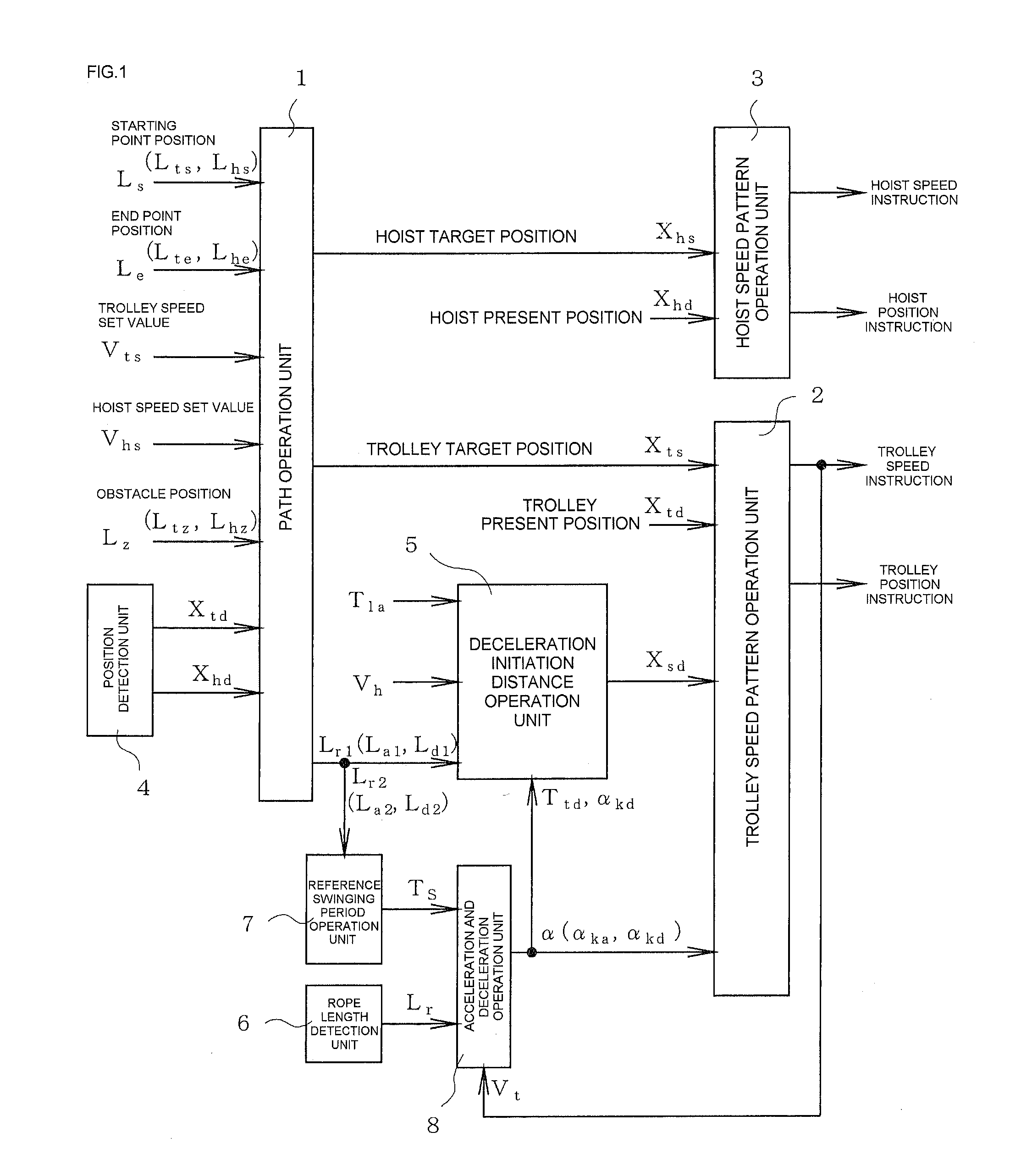
[0034]First, FIG. 1 is a block diagram of a driving control system of a crane including the swing stopping control system according to the embodiment. The driving control system is to be actualized by a CPU and an execution program thereof, for example.

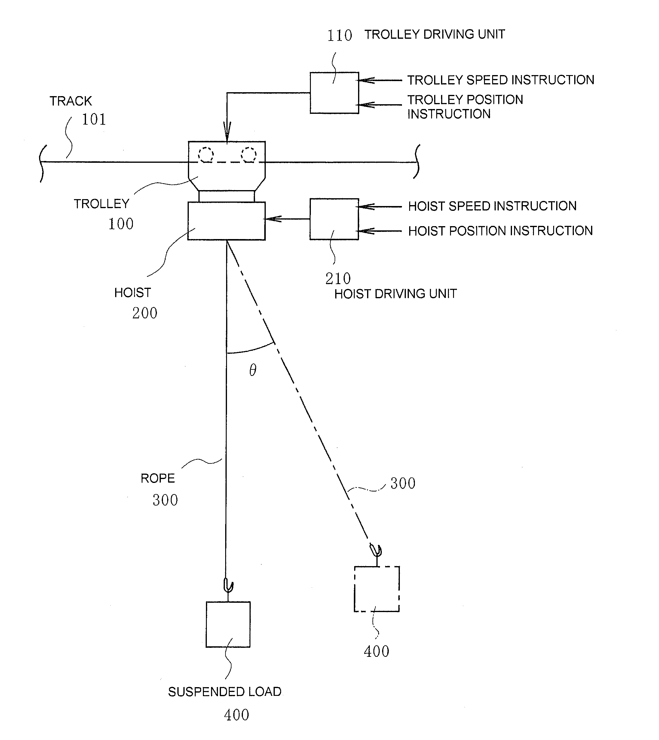
[0035]In FIG. 1, a path operation unit 1, on the basis of data of information of a crane starting position Ls as a starting position of a suspended load, a crane end point position Le as an end point position of the suspended load, a trolley speed set value Vts, a hoist speed set value Vhs, an obstacle position Lz, a trolley present position Xtd and a hoist present position Xhd, carries out operations on an optimum travel path of a suspended load for carrying the suspended load from a starting point position to an end point position while avoiding obstacles on a travel course and outputs the results of the operations as data of...


PUM


Abstract

A method of swing stopping control of a suspended load of a crane including a hoist and a trolley solves an equation of motion, given as an equation with respect to the deviation angle of a suspended load from the vertical direction when the trolley travels, for the trolley acceleration to thereby obtain the value of the acceleration or deceleration of the trolley, obtains speed patterns corresponding to the values of the acceleration or deceleration, drives the trolley according to the obtained speed patterns, and carries out control so that the deviation angle of the suspended load from the vertical direction becomes zero at the time when the acceleration or deceleration of the trolley is ended. Thus, even if the length of a rope holding the suspended load up is changed, a required speed pattern is produced to permit highly accurate positioning.

Description

CROSS-REFERENCE TO RELATED APPLICATIONS[0001]This application claims the benefit of Japanese Application No. 2011-058751, filed Mar. 17, 2011, in the Japanese Intellectual Property Office, the disclosure of which is incorporated herein by reference.BACKGROUND[0002]1. Field[0003]Embodiments of the present invention relate to a method of swing stopping control and a system of swing stopping control for carrying out swing stopping of a suspended load of a suspension type crane when carrying the suspended load to a target position by a trolley in the suspension type crane that is used for loading and unloading work at sites such as harbors, iron works and various kinds of factories.[0004]2. Description of the Related Art[0005]In loading and unloading work carried out by using a suspension type crane, from the view point of improving the efficiency of the loading and unloading work by reducing cycle time, not only positioning control that makes a suspended load correctly reach a target p...

Claims


Application Information

Patent Timeline
Patent Type & Authority Applications(United States)
IPC IPC(8): B66C13/06
CPCB66C13/06
Inventor UEDA, HIDETOKANEKO, TAKAYUKIYOSHIZAKI, HISASHI
Owner FUJI ELECTRIC CO LTD
Why Eureka
Try Eureka