Ceramic Crack Inspection

Inactive Publication Date: 2012-09-20
FENG HONG
View PDF5 Cites 37 Cited by
  • Summary
  • Abstract
  • Description
  • Claims
  • Application Information

AI Technical Summary

Benefits of technology

[0011]It is the objective of the present invention to solve the above-mentioned problems and to provide a reliable, low-cost, and easy-to-operate method, together with an a

Problems solved by technology

A crack will reduce the electrical conductivity, and t

Method used


Image

  • Ceramic Crack Inspection
  • Ceramic Crack Inspection
  • Ceramic Crack Inspection

Examples


Example

[0036]The illustrated embodiments of the invention now having been depicted in the above drawings, turn to the following detailed description of the invention and its various embodiments.

DETAILED DESCRIPTION OF THE INVENTION

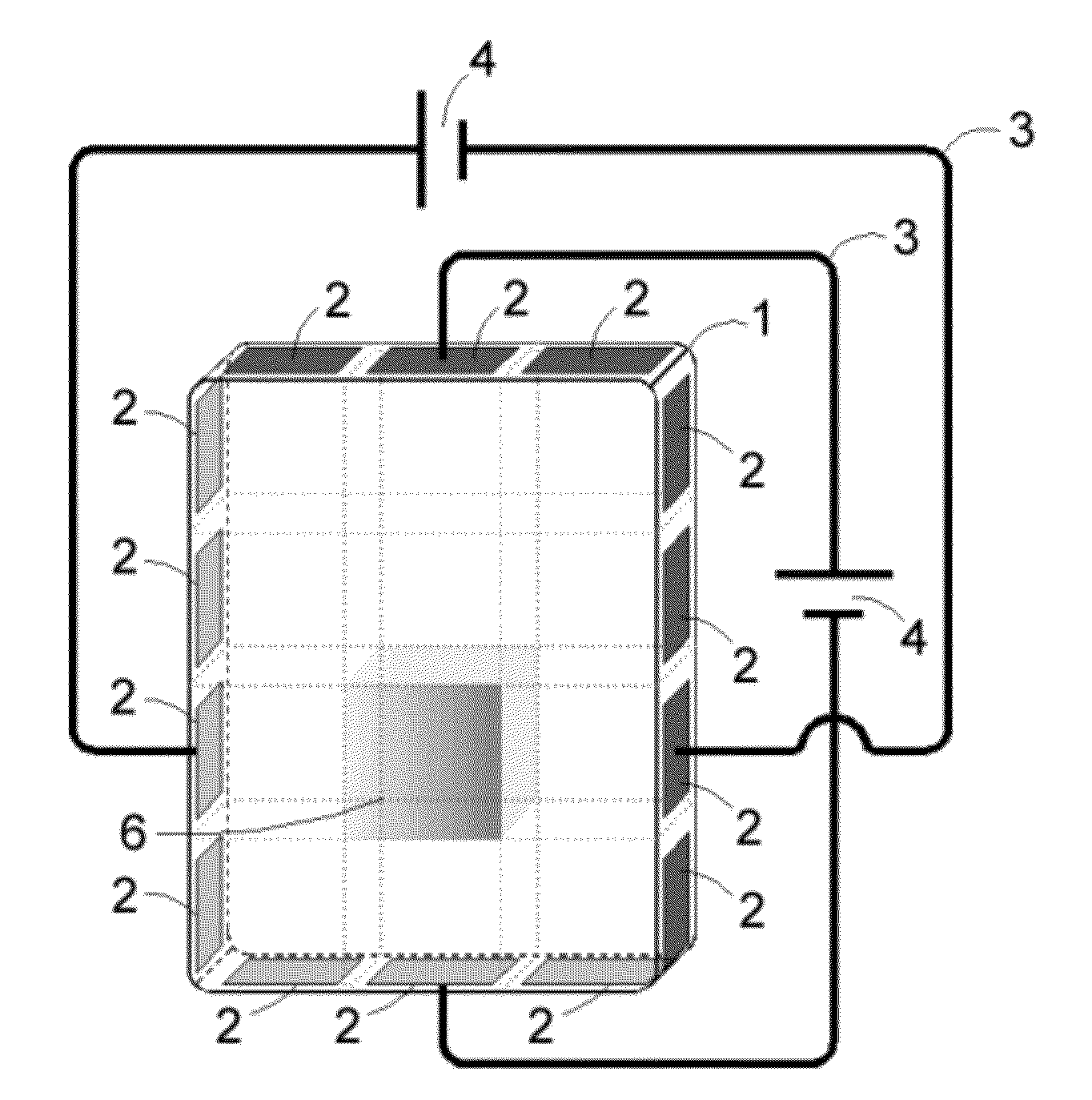
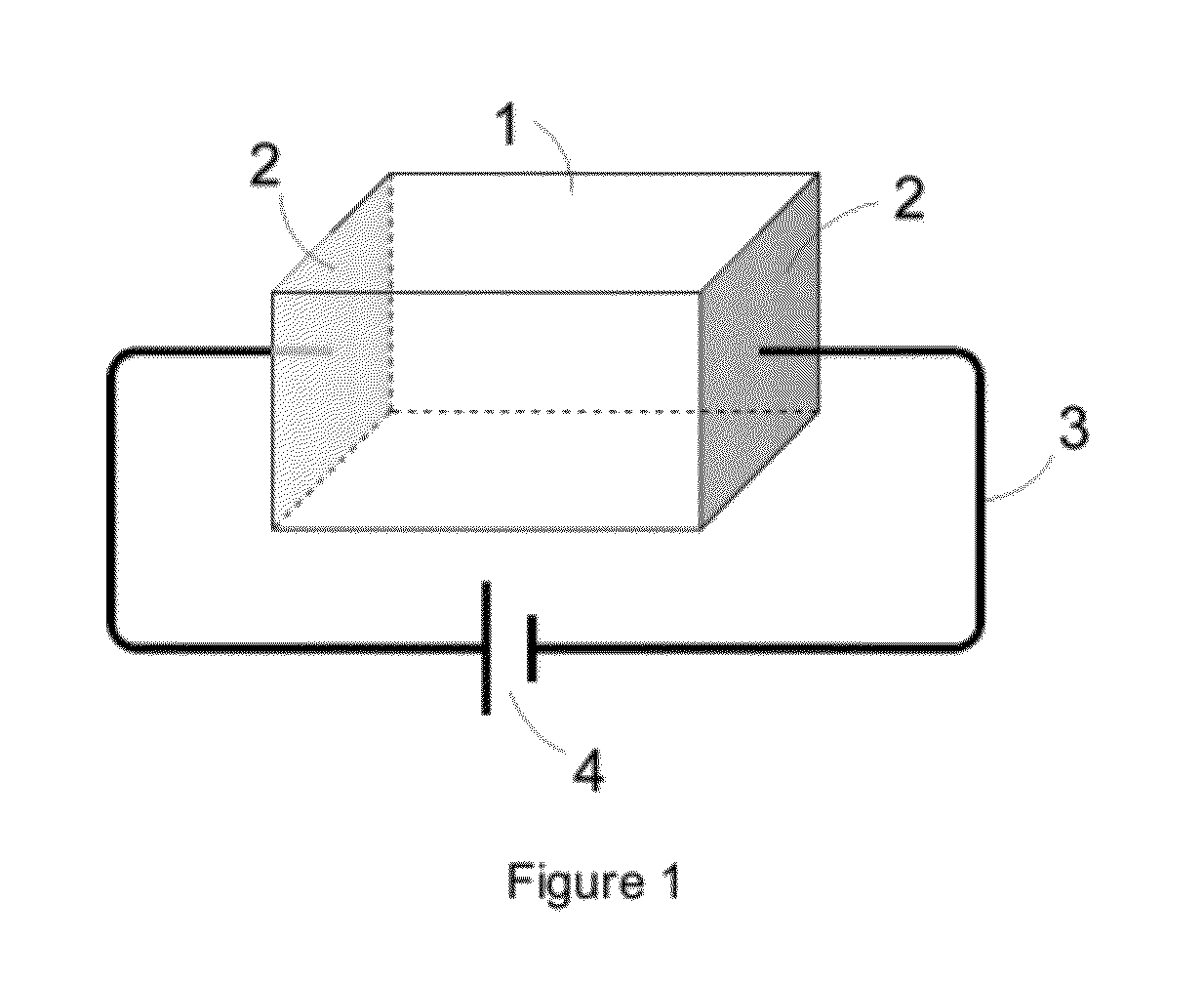
[0037]The basic process of inspecting a crack or cracks on a ceramic body according to the present invention is characterized in that (1) a pair of electrodes are affixed at two locations on one or more surfaces of a ceramic body; (2) electrical resistance of the ceramic body is measured through the pair of electrodes; and (3) the presence or absence of cracks in this portion of the ceramic body, as well as extent of the cracks, is judged based on a comparison result between the measured electrical resistance value and a reference value.

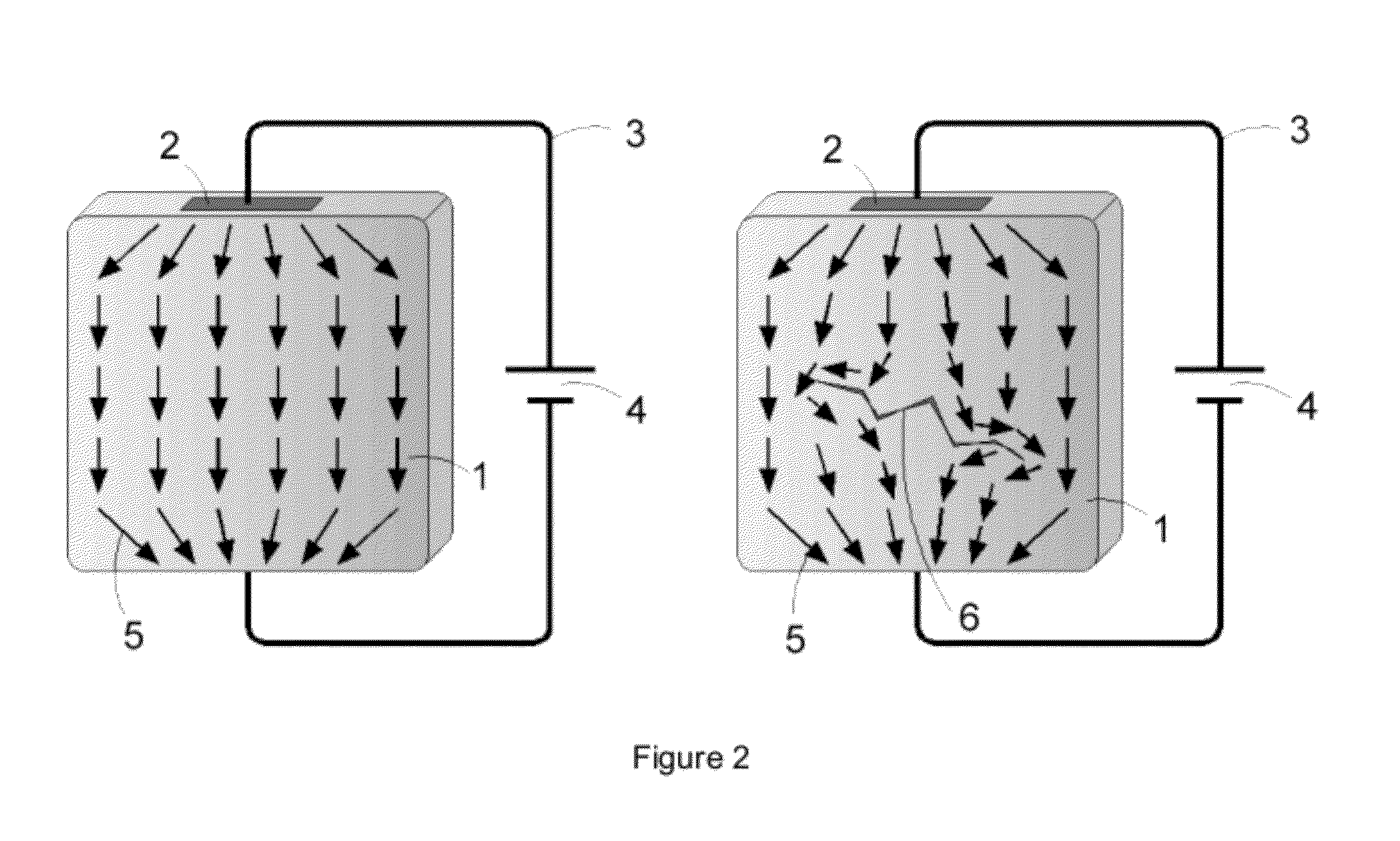
[0038]In order to increase the sensitivity to microscopic cracks and to further locate the cracks, (4) a plurality of electrode pairs are affixed on one or more surfaces of a ceramic body; (5) the electrical resistance is measured...


PUM


Abstract

A method and apparatus for non-destructive inspection including detection, quantification, and location of a surface or subsurface crack in a body made of advanced technical ceramics. The method and apparatus can detect all cracks in a ceramic body, including microscopic cracks, with a high sensitivity, accuracy and reliability, by measuring changes in electrical resistances through a plurality pairs of electrodes affixed on surfaces of the ceramic body. The extent of the cracks can be quantified and expressed as numerical data, and the location of the cracks can be identified. An automated inspection process enables a convenient, real-time, cost-effective crack inspection.

Description

CROSS-REFERENCE TO RELATED APPLICATIONS[0001]Not ApplicableSTATEMENT REGARDING FEDERALLY SPONSORED RESEARCH OR DEVELOPMENT[0002]Not ApplicableREFERENCE TO SEQUENCE LISTING, A TABLE, OR A COMPUTER PROGRAM LISTING COMPACT DISC APPENDIX[0003]Not ApplicableBACKGROUND OF THE INVENTION[0004]1. Field of the Invention[0005]The present invention relates to a method and an apparatus for inspecting crack in a manufactured body made of advanced technical ceramics, such as a ceramic ballistic armor plate.[0006]2. Description of the Prior Art[0007]Advanced technical ceramics are valued for their hardness, strength, wear resistance, thermal and chemical stability, light weight and abrasion resistance, and hence find wide use in such applications as ballistic protective armor systems, high-performance engines, semiconductor equipment, and wear components of equipment in oil, gas, and mining operations. However, due to the brittle nature, advanced ceramics are subject to cracking upon impact. Cracks...

Claims


Application Information

Patent Timeline
IPC IPC(8): G01R27/08
CPCG01N27/20
Inventor FENG, HONG
Owner FENG HONG
Why Eureka
Try Eureka