Latency Analysis of Traffic Passing Through an Ethernet Switch

Active Publication Date: 2012-09-20
ARISTA NETWORKS
View PDF6 Cites 4 Cited by
  • Summary
  • Abstract
  • Description
  • Claims
  • Application Information

AI Technical Summary

Benefits of technology

[0008]Accordingly, in one aspect, the present invention provides an improved latency analysis and monitoring technique that allows real time monitoring of latency and congestion conditions in both individual network switches and in a network of networking sw

Problems solved by technology

However, under congestion, queuing delays add to the forwarding latency and add variability that has been hard to measure, or predict, at any given time.
These common techniques, however, do not provide any information about the latency of the network.
In addition, network latency, as measured by round trip from point A to point B provides the average latency over a time window but does not provide any further deta

Method used


Image

  • Latency Analysis of Traffic Passing Through an Ethernet Switch
  • Latency Analysis of Traffic Passing Through an Ethernet Switch
  • Latency Analysis of Traffic Passing Through an Ethernet Switch

Examples


Example

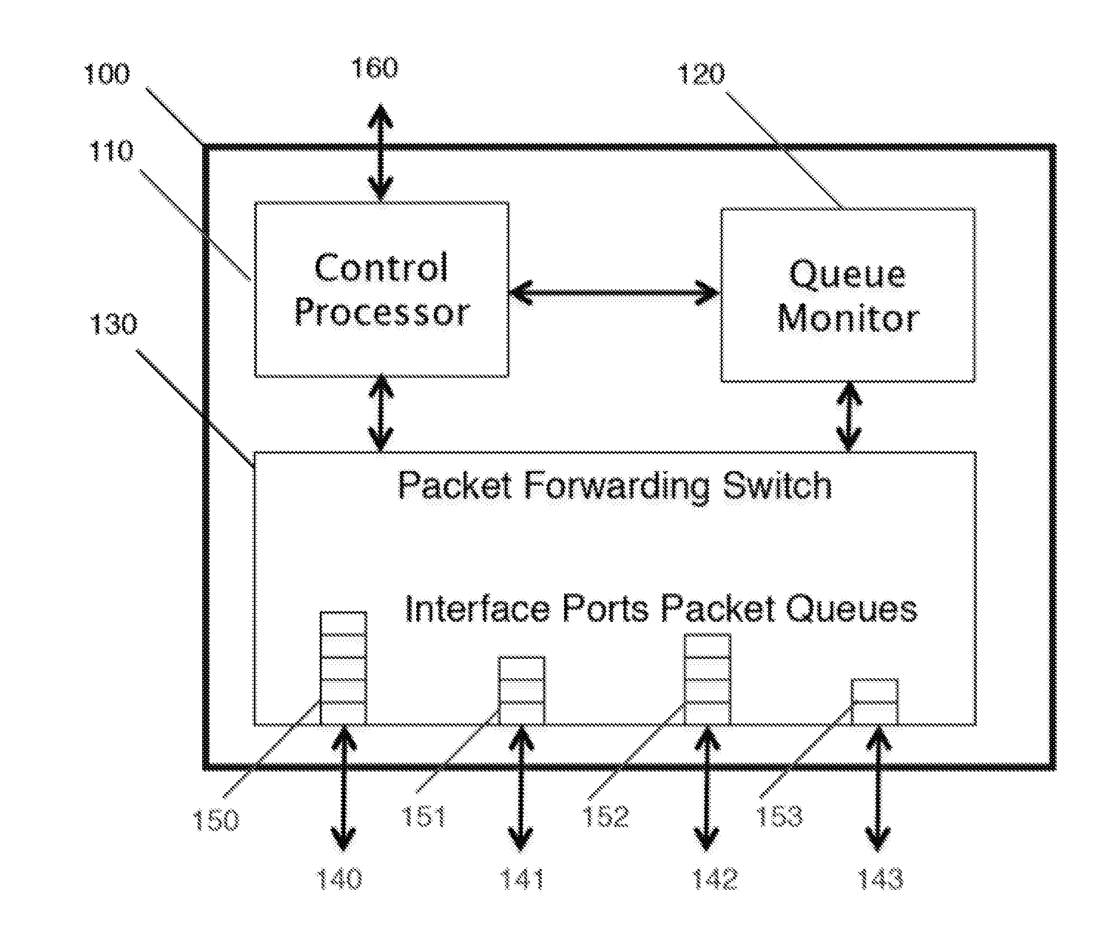
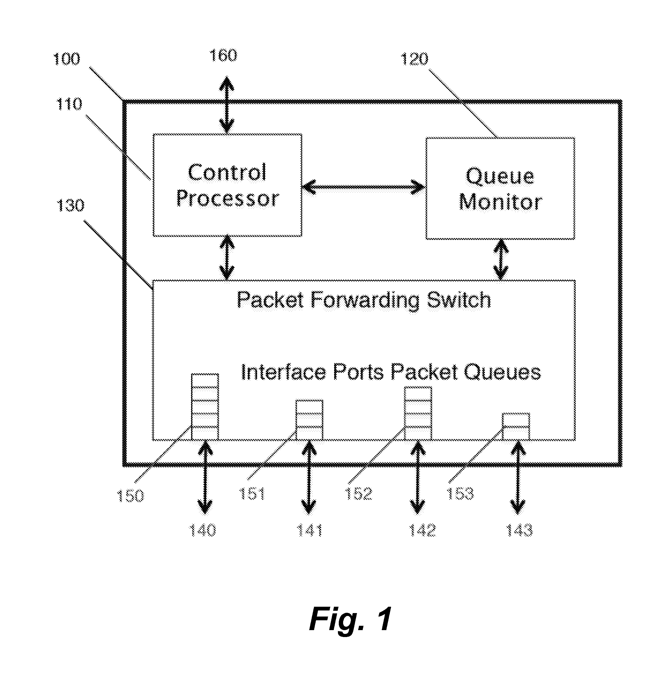
[0016]FIG. 1 shows the internal architecture of a network switch 100 comprised of Control Processor 110, Queue Monitor 120, and Packet forwarding switch 130, each of which is communicatively connected to the other two.

[0017]As shown, Packet forwarding switch 130 has interface ports 140, 141, 142, 143 that can be used to connect the switch 100 to other network switches, routers, servers, or other network devices. Associated with the interface ports are corresponding packet queues 150, 151, 152, 153 located in the packet forwarding switch 130. The Control Processor 110 has a Management Port 160 which allows the switch 100 to connect to a management network.

[0018]FIG. 3 illustrates a process for measuring and recording the switch latency by taking into account the queue depth of each interface.

[0019]In step 300, at microsecond intervals or less, Queue Monitor 120 reads the queue depth of Packet Queues 150 through 153 and records the queue depth in bytes along with the exact time of the...


PUM


Abstract

A method for accurately measuring, recording and reporting latency of an Ethernet switch is disclosed. Various packet queues in the switch are monitored at any given time and forwarding latency is calculated. Latency data from multiple switching elements in a network is collected to provide end-to-end forwarding latency of a system.

Description

CROSS-REFERENCE TO RELATED APPLICATIONS[0001]This application claims priority from U.S. Provisional Patent Application 61 / 452634 filed Mar. 14, 2011, which is incorporated herein by reference.FIELD OF THE INVENTION[0002]The present invention relates generally to techniques for networking test and measurement. More particularly, it relates to measuring and recording the latency of Ethernet switches under load.BACKGROUND OF THE INVENTION[0003]An Ethernet switch commonly has a fixed forwarding latency for packet transmission. However, under congestion, queuing delays add to the forwarding latency and add variability that has been hard to measure, or predict, at any given time.[0004]There have been many advancements in managing congestion in a network using quality of service and various congestion notifications. Examples of the state of the art in this field are the teachings of U.S. Pat. No. 6,560,648, US 2010 / 0293243, and US 2011 / 0019558.[0005]These common techniques, however, do not...

Claims


Application Information

Patent Timeline
IPC IPC(8): H04L12/26H04L47/30
CPCH04L43/0852H04L43/106H04L47/11H04L49/555H04L47/30H04L49/351H04L47/28
Inventor DUDA, KENNETH J.SADANA, ANSHULHOLBROOK, HUGH W.
Owner ARISTA NETWORKS
Why Eureka
Try Eureka