Compact quick coupling mechanism for tool attachment

Active Publication Date: 2012-09-20
BRANDT IND
View PDF19 Cites 8 Cited by
  • Summary
  • Abstract
  • Description
  • Claims
  • Application Information

AI Technical Summary

Benefits of technology

[0006]It is an object of the present invention to provide a compact quick coupling apparatus for coupling a tool to a machine that overcomes problems in the prior art.
[0007]The present invention provides a compact quick coupling apparatus for coupling a tool to a tool arm of a tool manipulating machine. The apparatus comprises a coupler member adapted to be attached to the tool arm, and configured to engage a mounting bracket extending out from the tool. A wedge is mounted on the coupler member and is movable, when the coupler member and mounting bracket are engaged, from a closed position where the wedge is engaged in a groove on the mounting bracket and where a tapered side of the wedge bears against a corresponding tapered side of the groove to draw the coupler member into engagement with the mounting bracket, to an open position where the wedge is removed from the groove. The wedge moves in an opening direction when moving from the closed position to the open position, and moves in a closing direction when moving from the open position to the closed position. A wedge bias element extends in the opening direction from the wedge, the wedge bias element operative to continuously exert a wedge bias force on the wedge in the closing direction to push the wedge into the groove, and operative to exert the wedge bias force on the wedge when the wedge is in the closed position such that the wedge bias force maintains the wedge in the closed position. A latch bias element is operative to exert a latch bias force urging a safety la

Problems solved by technology

The area becomes quite crowded when the mechanism

Method used


Image

  • Compact quick coupling mechanism for tool attachment
  • Compact quick coupling mechanism for tool attachment
  • Compact quick coupling mechanism for tool attachment

Examples


Embodiment Construction

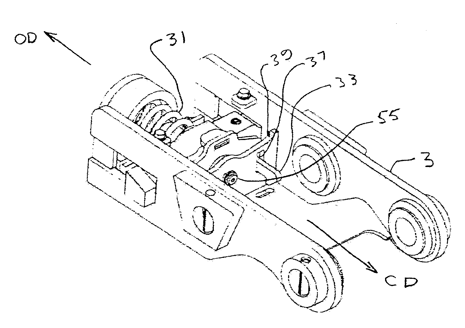
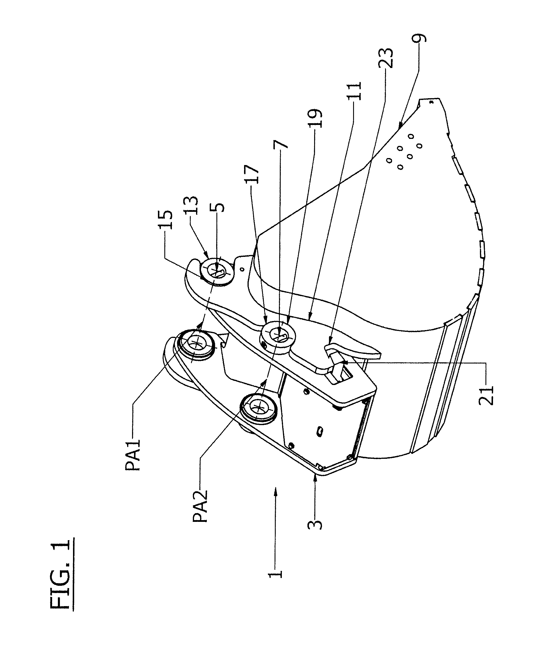
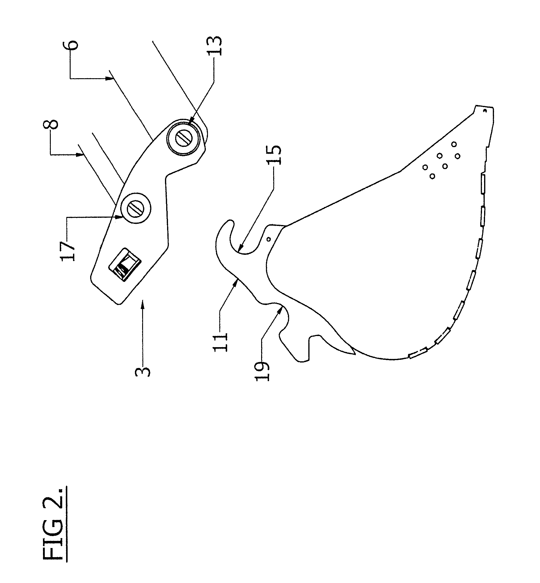
[0018]FIGS. 1-5 illustrate the operation of an embodiment of a quick coupling apparatus 1 of the present invention. The apparatus 1 comprises a coupler member 3 that is attached to a tool manipulating machine at the tool attachment point. The illustrated apparatus 1 is adapted for attachment to the end of the hoe arm of an excavator. The attachment is conventional, and the hoe arm is not illustrated. The coupler member 3 is attached by a first pin through first pin aperture 5 and through a corresponding aperture on the end of the hoe arm 6, and then by a second parallel pin through second pin aperture 7 and through a corresponding aperture on the end of the hydraulic tool cylinder 8 that extends and retracts to pivot the apparatus 1 about the end of the hoe arm.

[0019]The coupler member 3 is configured to engage mounting brackets 11 that extend out from the bucket 9. A first set of lugs 13 on the coupler member 3 are manipulated from the unattached position of FIG. 2 into engagement ...


PUM


Abstract

A compact quick coupling apparatus has a wedge movable between closed and open positions. A wedge spring extends in the opening direction from the wedge and urges the wedge in the closing direction. A latch spring urges a safety latch to a latched position to prevent the wedge from moving. A single acting hydraulic cylinder extends through the wedge and extends in the opening direction from the wedge. As the hydraulic cylinder extends it first moves the safety latch to the unlatched position, and then moves the wedge in the opening direction. When pressurized fluid is released from the hydraulic cylinder, it retracts and the wedge moves in the closing in response to the wedge spring until the wedge reaches the closed position, and then the hydraulic cylinder further retracts in response to the latch spring and the safety latch moves to the latched position.

Description

[0001]This invention is in the field of machines such as hoe excavators and in particular a compact mechanism for coupling and uncoupling a tool particularly to smaller versions of such machines, for example for coupling an excavator bucket to the excavator hoe atm of a mini-excavator.BACKGROUND[0002]In many types of machines different tools are coupled to and then uncoupled from the machine to accomplish different tasks. For example, a hoe excavator with a hoe arm may have a variety of buckets of various widths and shapes that are suitable for particular different tasks. Depending on the task, the desired bucket is coupled to the end of the hoe arm of the excavator, and when that task is finished the bucket will be uncoupled and a different bucket will be coupled to the arm to accomplish the next task. In addition to various buckets, other tools such as pneumatic hammers, post hole augers, and the like are often attached to the excavator arm to increase the variety of tasks that th...

Claims


Application Information

Patent Timeline
IPC IPC(8): F16D1/10
CPCY10T403/599E02F3/3631E02F3/365Y10T403/22E02F3/3663E02F3/364Y10T403/591Y10T403/602
Inventor STOLLERY, RANDAL D.
Owner BRANDT IND
Why Eureka
Try Eureka