Turbocharger

a turbocharger and turbocharger technology, applied in the field of turbochargers, can solve the problems of reducing the turbocharger efficiency, and achieve the effect of improving the turbocharger efficiency

Active Publication Date: 2012-09-20
IHI CORP
View PDF14 Cites 26 Cited by
  • Summary
  • Abstract
  • Description
  • Claims
  • Application Information

AI Technical Summary

Benefits of technology

[0026]Effects obtained according to the invention are described below.
[0027]According to the invention, since the exhaust gas can be prevented from leak

Problems solved by technology

However, the exhaust gas inside the turbine scroll flow path leaks to an outlet side of th

Method used


Image

  • Turbocharger
  • Turbocharger
  • Turbocharger

Examples


Embodiment Construction

[0032]Hereinafter, a turbocharger according to an embodiment of the invention will be described with reference to the drawings.

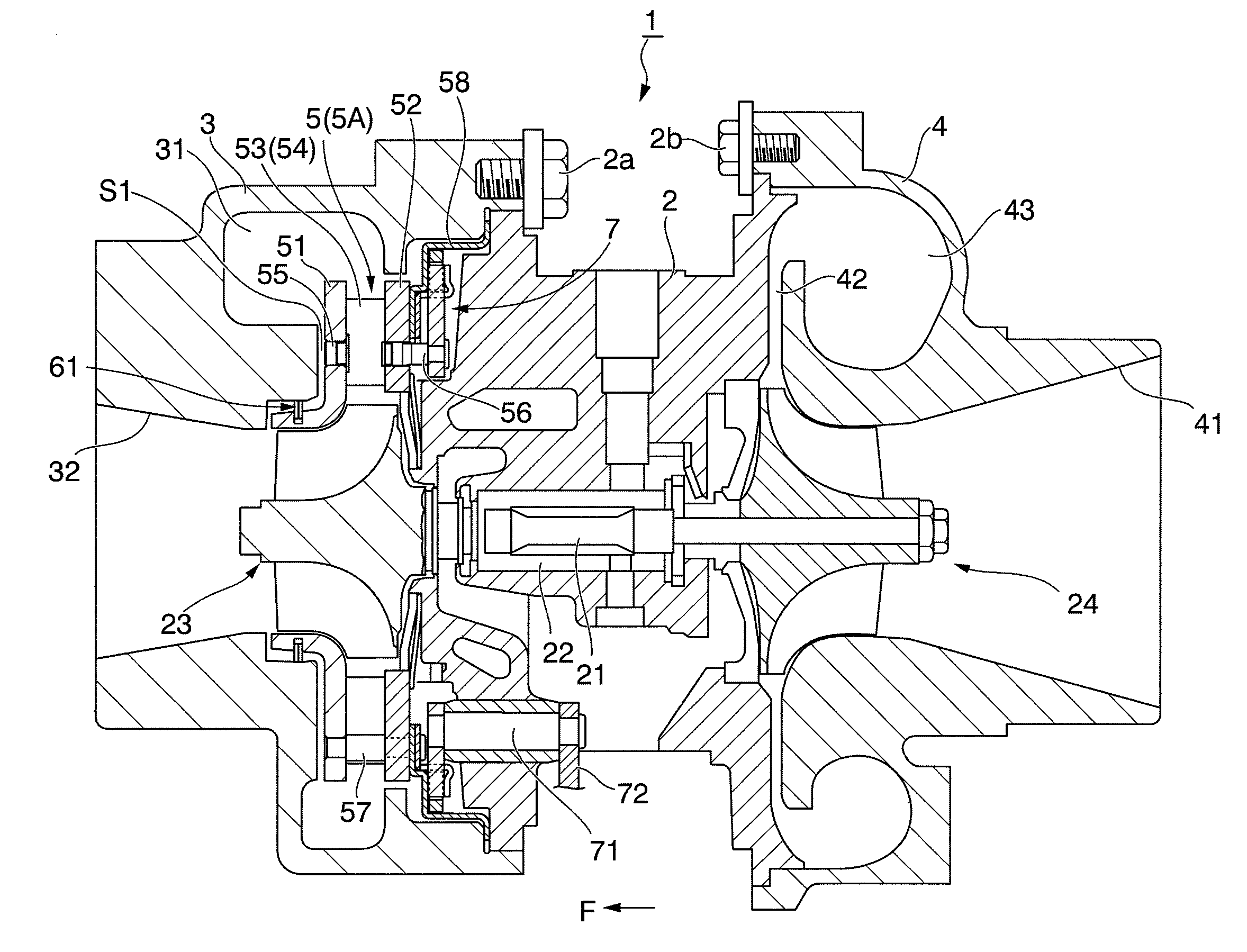
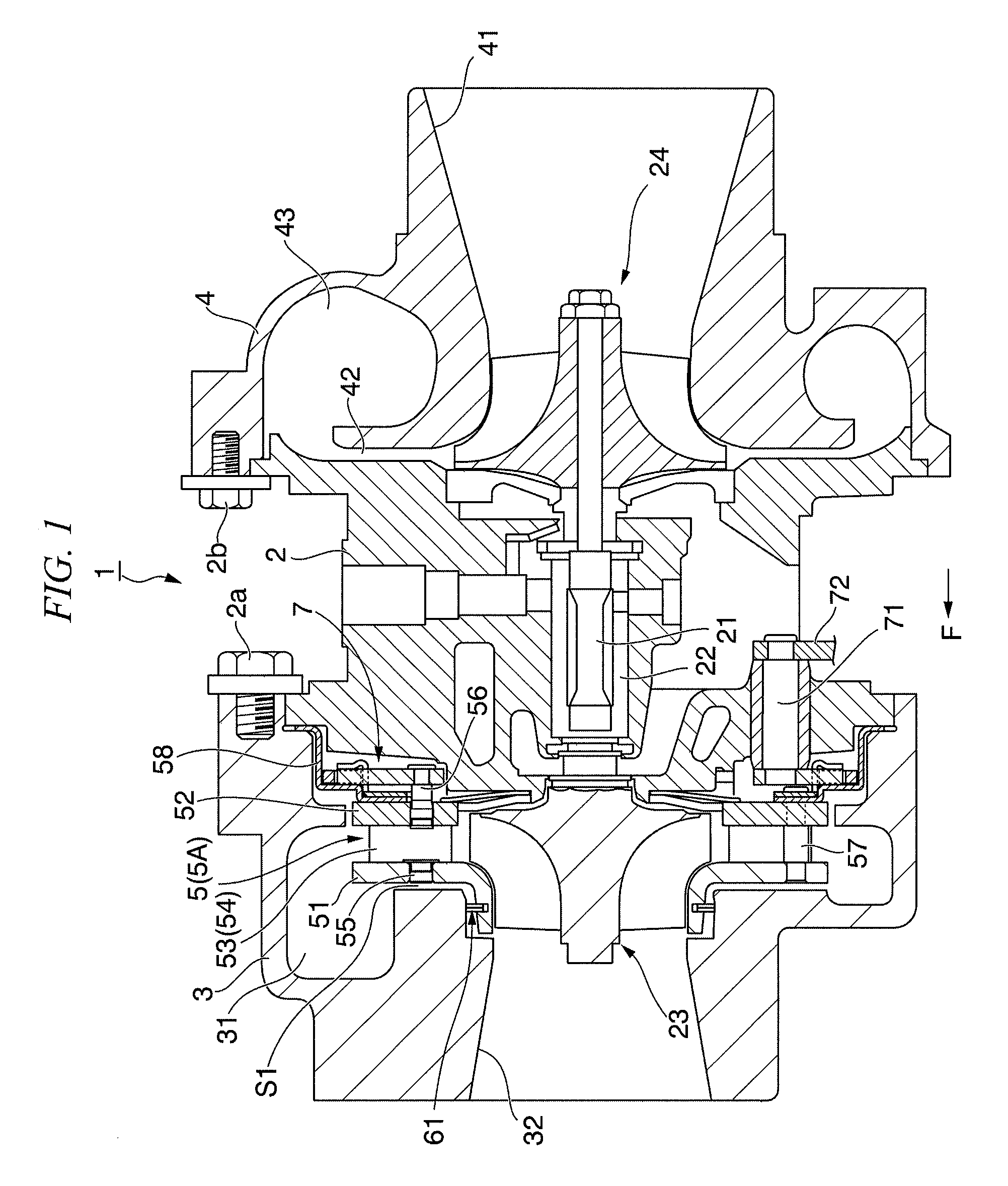
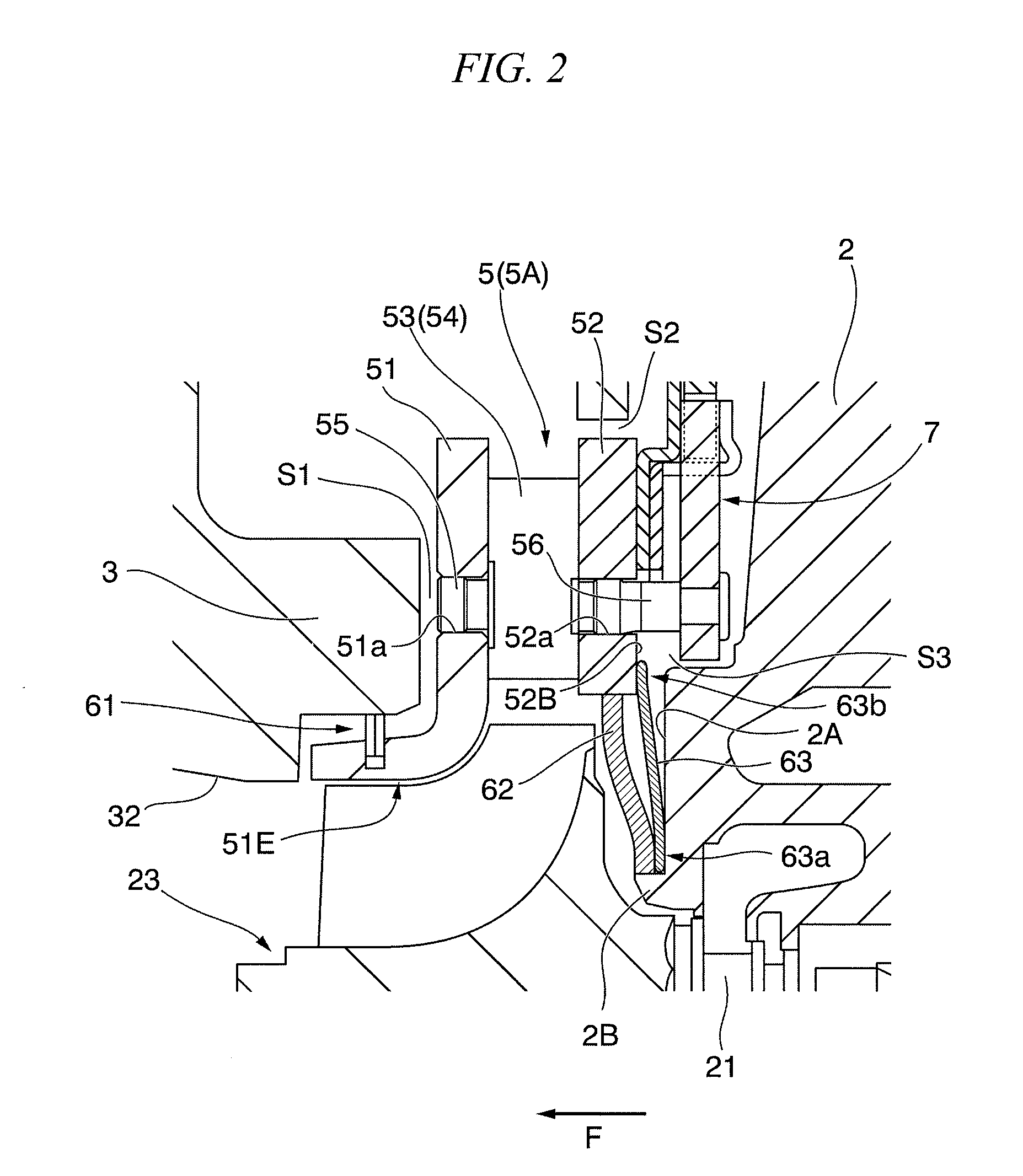
[0033]FIG. 1 is a schematic view illustrating an overall configuration of a turbocharger 1 of the embodiment, FIG. 2 is an enlarged view around a variable nozzle unit 5 in FIG. 1, FIG. 3 is a schematic view of a disc spring 63 in the embodiment, (a) of FIG. 3 is a plan view of the disc spring 63 and (b) of FIG. 3 is a cross-sectional view taken along line X-X of (a) of FIG. 3. In addition, an arrow F in the drawings described above illustrates a forward direction.

[0034]First, the overall configuration of the turbocharger 1 of the embodiment will be described with reference to FIG. 1.

[0035]As shown in FIG. 1, the turbocharger 1 of the embodiment is a variable geometry turbocharger supercharging air, which is supplied to an engine (not shown), by using energy of exhaust gas introduced from the engine.

[0036]The turbocharger 1 includes a bearing housing 2, a tur...


PUM


Abstract

A variable geometry turbocharger includes a bearing housing rotatably supporting a turbine impeller; and an exhaust nozzle changing the flow rate of an exhaust gas supplied to the turbine impeller, wherein the exhaust nozzle has an exhaust inlet wall disposed at the bearing housing side, the turbocharger has a seal member exhibiting a ring shape and sealing a gap formed between the bearing housing and the exhaust inlet wall, and an inner circumferential edge of the seal member firmly contacts the bearing housing and an outer circumferential edge of the seal member firmly contacts the exhaust inlet wall.

Description

TECHNICAL FIELD[0001]The present invention relates to a turbocharger that supercharges air which is supplied to an engine using the energy of exhaust gas discharged from the engine, and specifically to a variable geometry turbocharger.BACKGROUND ART[0002]Conventionally, the variable geometry turbocharger is known which can improve the performance of the engine over a wide range from a low revolution region to a high revolution region.[0003]Here, a variable geometry turbocharger is disclosed in Patent Document 1.[0004]The above described turbocharger has a configuration in which a turbine housing and a compressor housing are integrally connected via a bearing housing, and a turbine impeller disposed inside the turbine housing and a compressor impeller disposed inside the compressor housing are connected by a rotating shaft that is disposed so as to be rotatable inside the bearing housing.[0005]An exhaust gas inlet port is disposed at the turbine housing, and the exhaust gas that flow...

Claims


Application Information

Patent Timeline
IPC IPC(8): F04D29/08F04D29/42
CPCF01D17/165F02B37/24F02C6/12F05D2230/642F02M59/06Y02T10/144F05D2240/55F02C7/28Y02T10/12F01D17/16
Inventor MATSUYAMA, YOSHIMITSU
Owner IHI CORP
Why Eureka
Try Eureka