System for detecting a short circuit associated with a direct current bus

a short circuit and bus technology, applied in the field of system for detecting a short circuit associated with a direct current bus, can solve problems such as damage to the winding of the electric motor or other circuitry within the inverter

Active Publication Date: 2012-09-20
DEERE & CO
View PDF5 Cites 16 Cited by
  • Summary
  • Abstract
  • Description
  • Claims
  • Application Information

AI Technical Summary

Benefits of technology

[0004]In accordance with one embodiment, a system is capable of detecting a short circuit associated with a direct current bus. The system comprises a direct current bus having a positive terminal and a negative terminal. A first switching transistor and a second switching transistor have their respective switched terminals connected (or coupled) in series with respect to each other between the positive terminal and the negative terminal. A primary supply is arranged to generate a test voltage that is lower than an operational voltage of the direct current bus. The test voltage is applied between the positive terminal and the negative terminal of the direct current bus. A primary thermal circuit is associated with the supply for detecting whether the supply exceeds an operational temperature threshold. The thermal circuit provides a signal or logic level state indicative of a detected short circuit in the direct current bus if the primary supply exceeds the operational temperature threshold.

Problems solved by technology

If one or more power switching semiconductors fail in a closed state, a short circuit may be established between the opposite polarity terminals of the direct current data bus or between a direct current terminal and a normally alternating current output of the inverter, which can damage a winding of the electric motor or other circuitry within the inverter.

Method used


Image

  • System for detecting a short circuit associated with a direct current bus
  • System for detecting a short circuit associated with a direct current bus
  • System for detecting a short circuit associated with a direct current bus

Examples


Embodiment Construction

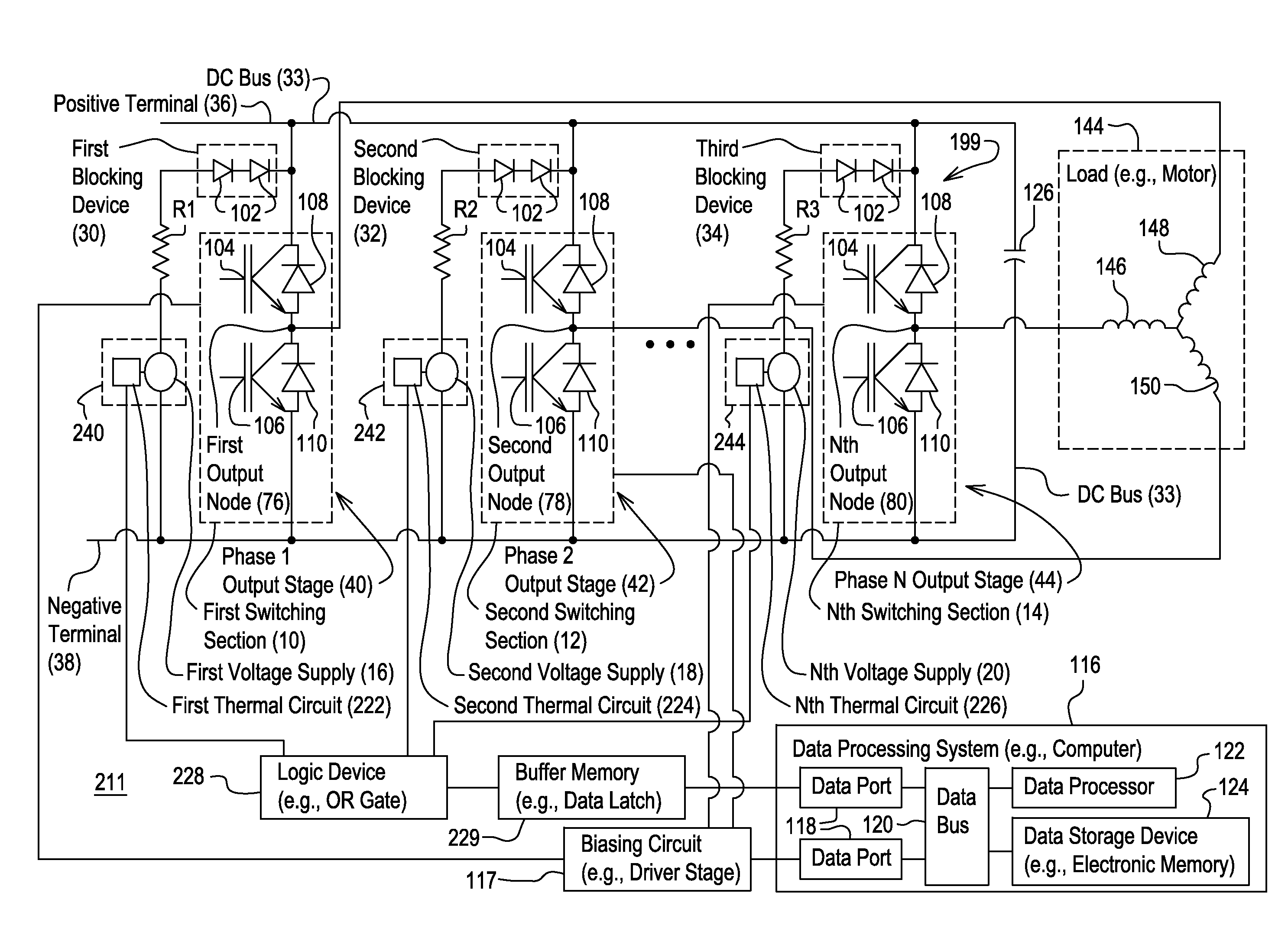
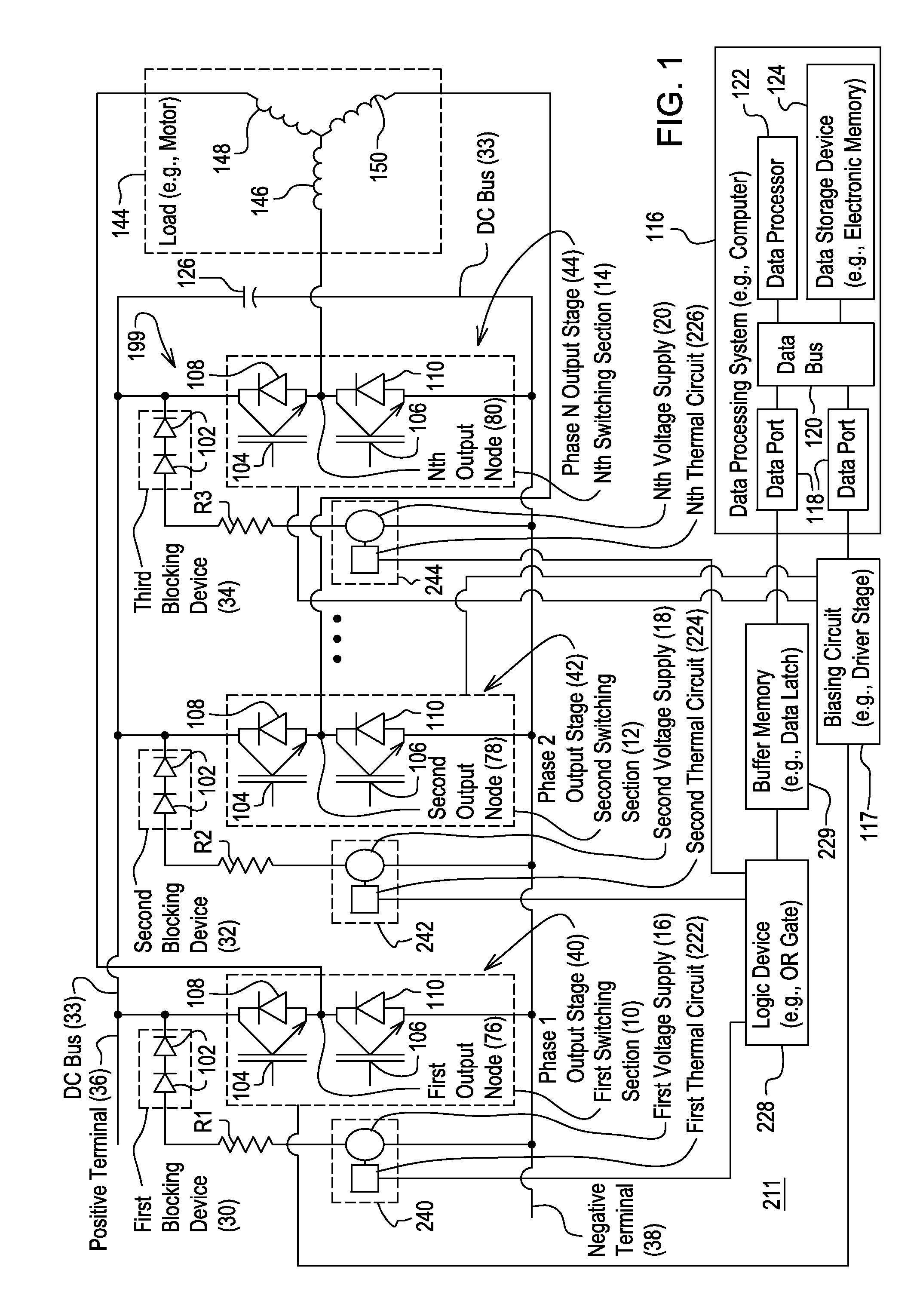
[0007]In accordance with one embodiment, FIG. 1 shows a system 211 that is capable of detecting a short circuit associated with a direct current bus 33. The system comprises a direct current bus 33 having a positive terminal 36 and a negative terminal 38. The inverter 199 may have one or more phases or subassemblies, where each phase or subassembly provides a separate output signal to a corresponding output terminal of the inverter 199. Each phase of the inverter 199 has a pair of switching transistors (104, 106), a corresponding voltage supply (16, 18, 20), and a corresponding thermal circuit (222, 224, 226). The switching transistors (104, 106) are configured to receive direct current power from the direct current bus 33. One or more output terminals of the inverter 199 are coupled to the load 144 (e.g., motor). The inverter 199 may control the switching transistors (104, 106) to modulate the output signal applied to the load 144 or motor, which supports the control of the rotatio...


PUM


Abstract

The system comprises a direct current bus having a positive terminal and a negative terminal. A first switching transistor and a second switching transistor have their respective switched terminals connected in series with respect to each other between the positive terminal and the negative terminal. A primary supply is arranged to generating a test voltage that is lower than an operational voltage of the direct current bus. The test voltage is applied between the positive terminal and the negative terminal of the direct current bus. A primary thermal circuit is associated with the supply for detecting whether the supply exceeds an operational temperature threshold. The thermal circuit provides a signal or logic level state indicative of a detected short circuit in the direct current bus if the primary supply exceeds the operational temperature threshold.

Description

[0001]This document claims priority based on U.S. provisional application Ser. No. 61 / 453,164, filed on 16 Mar. 2011 and entitled SYSTEM FOR DETECTING A SHORT CIRCUIT ASSOCIATED WITH A DIRECT CURRENT BUS, under 35 U.S.C. 119(e).FIELD OF THE INVENTION[0002]This invention relates to system for detecting a short circuit associated with a direct current bus.BACKGROUND[0003]In the prior art, an inverter is used to convert a direct current voltage on a direct current data bus to one or more alternating current signals that control an electric motor. In certain prior art configurations, the inverter comprises one or more power switching semiconductors that may fail in an open state or a closed state. If one or more power switching semiconductors fail in a closed state, a short circuit may be established between the opposite polarity terminals of the direct current data bus or between a direct current terminal and a normally alternating current output of the inverter, which can damage a win...

Claims


Application Information

Patent Timeline
Patent Type & Authority Applications(United States)
IPC IPC(8): G06F19/00G01R31/02
CPCG01R31/025G01R31/42G01R31/52
Inventor SINGH, BRIJ N.
Owner DEERE & CO
Why Eureka
Try Eureka