
Power system

a power system and battery technology, applied in the field of power systems, can solve the problems of inability to convert the entire capacity of battery discharge into commercial alternating power, inability of the power system to surpass the capacity of the battery discharge, and inability to meet the needs of the driver

Active Publication Date: 2010-10-28
HONDA MOTOR CO LTD
View PDF5 Cites 36 Cited by
  • Summary
  • Abstract
  • Description
  • Claims
  • Application Information

AI Technical Summary

Benefits of technology

[0011]Herein, the power needed to drive an accessory device or the like of the power supply unit is supplied from the electric accumulator, particularly at a low temperature, the power from the electric accumulator will be consumed by an air conditioner or the like of the power supply unit, the capacity of charge of the electric accumulator will be decreased. However, by calculating the amount of power needed to heat the power supply unit, setting the first discharge threshold by adding the calculated amount of power to the discharge threshold of the electric accumulator, and controlling the power supply from the electric accumulator to the first power supply portion to be greater than the first discharge threshold, it can be avoided that the electric accumulator might supply power to the outside by surpassing a discharge threshold thereof, or the power supply to the outside from the electric accumulator according to the discharge threshold might be shut off suddenly. Thereby, according to the power system of the present invention, the power can be supplied steadily to the outside even at a low temperature.
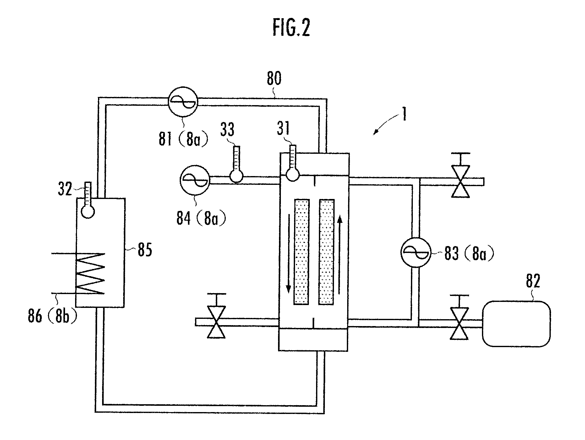
[0013]According to the power system of the second aspect of the present invention, in addition to the fuel cell itself, the coolant for cooling the fuel cell is also needed to be heated at a low temperature. Therefore, if the measured temperature of the coolant is below the temperature threshold where the heating is needed, by calculating the amount of power needed to heat the coolant, setting the new second discharge threshold by adding the calculated amount of power to the discharge threshold of the electric accumulator, and controlling the power supply from the electric accumulator to the first power supply portion to be greater than the second discharge threshold, the power can be supplied steadily to the outside even at a low temperature.
[0016]After a fuel cell is actuated, a given time interval is need for it to have a rated output of a predefined value. According to the power system of the present invention, the power is supplied to the first power supply portion from the electric accumulator before the actuation of the fuel cell; therefore, the first power supply portion can be available for use without waiting for the fuel cell to have the rated output.
[0019]Since the second battery with a greater capacity of charge is discharged thereafter, the decreasing rate of the capacity of charge due to the discharge is smaller, which makes it possible to supply power to the first power supply portion steadily over a long period. By setting a new second discharge threshold in consideration of the power consumed for heating so that the predefined output is available before the capacity of charge drops below the new second discharge threshold, it is possible for the fuel cell to supply power to the first power supply portion steadily even during the actuation interval at a low temperature, and the capacity of charge of the second battery can be prevented from dropping below the new discharge threshold.
[0020]Thirdly, by discharging the fuel cell after the predefined output thereof has become available, it is possible for the fuel cell to supply power to the first power supply portion and to charge the capacitor and the secondary battery meanwhile.

Problems solved by technology

However, according to the power system only with the battery as the power source, although it is easy to provide the commercial alternating power converted from a direct voltage supplied from the battery after being boosted, it is impossible for the power system to surpass a capacity of discharge of the battery.
In the case where the power generated from the rotation of the motor driven by the engine is provided, if the engine is not ignited on, the power cannot be generated therefrom for use; and consequently, it is impossible for the power system to surpass the capacity of discharge of the battery.
Moreover, since it is necessary for the battery to supply power for igniting the engine or the like, it is impossible to convert the entire capacity of discharge of the battery into the commercial alternating power.
Particularly, the power will be consumed by air conditioner or the like at a low temperature, there is the danger that the battery might supply power to the outside by surpassing a discharge threshold thereof, or the power supply to the outside from the battery according to the discharge threshold might be shut off suddenly.

Method used


Image

  • Power system
  • Power system
  • Power system

Examples


Embodiment Construction

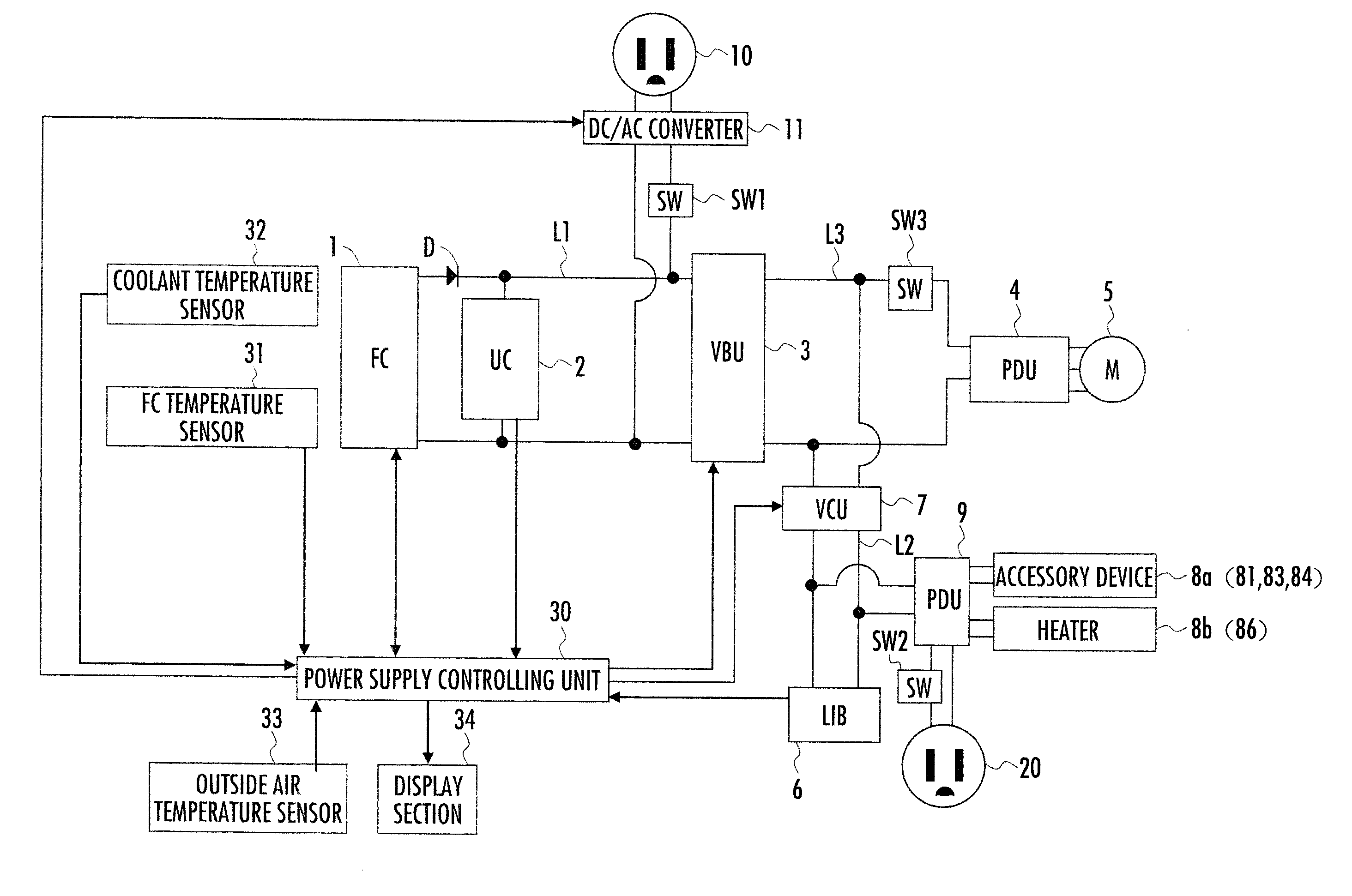
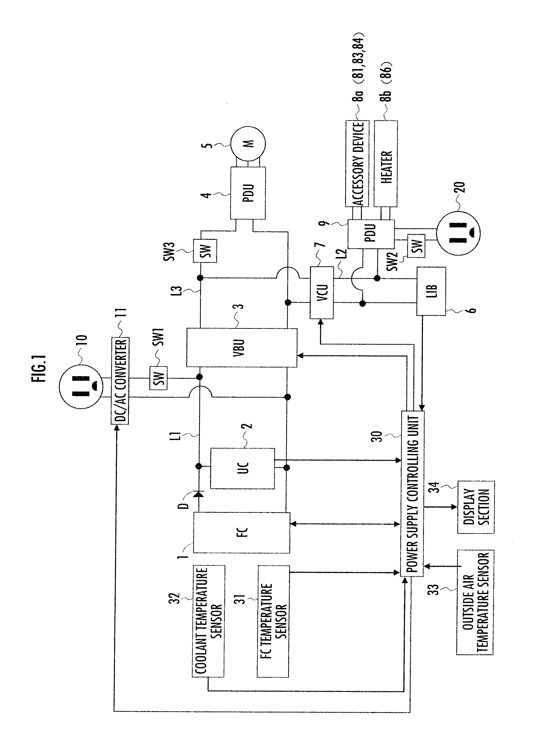
[0034]As illustrated in FIG. 1, a power system of the present embodiment is disposed in a fuel cell vehicle (corresponds to a vehicle of the present invention). The power system is provided with a fuel cell 1 (corresponds to a power supply unit of the present invention), a double-layer electric capacitor 2 (hereinafter, simply referred to as the capacitor 2) connected in parallel to the fuel cell 1, a voltage boost unit 3 (corresponds to a first voltage boost unit of the present invention), a secondary battery 6 (a lithium-ion battery in the present embodiment), and a voltage converter 7 (corresponds to a second voltage boost unit of the present invention). An input section of the voltage boost unit 3 is connected to both the fuel cell 1 and the capacitor 2, and an output section thereof is connected to an electric motor 5 via a PDU 4 (Power Drive Unit). An input section of the voltage converter 7 is connected to the voltage boost unit 3 and an output section thereof is connected to...


PUM


Abstract

Provided is a power system capable of supplying power steadily to the outside even at a low temperature. A power supply unit disposed in the power system is configured to calculate an amount of power needed to heat a fuel cell to a temperature threshold when the temperature thereof measured by an FC sensor is below the temperature threshold, set an SOC lower limit by adding the calculated amount of power to a discharge threshold of a secondary battery, and control the power supply to a first power supply portion in the range of the SOC lower limit.

Description

BACKGROUND OF THE INVENTION[0001]1. Field of the Invention[0002]The present invention relates to a power system disposed in a vehicle.[0003]2. Description of the Related Art[0004]Hitherto, there has been known a power system disposed in a vehicle (for example, refer to Japanese Patent Laid-open No. 2006-288129). In the power system, a battery is used as a power source, a voltage of the battery is boosted and supplied to a power line and the voltage supplied to the power line is converted into a commercial alternating voltage by a DC / AC converter for outputting. There has also been known a power system (for example, refer to Japanese Patent Laid-open No. 2006-20455) which converts power generated by a motor driven by an engine or power of a battery into a commercial alternating power via an AC inverter.[0005]However, according to the power system only with the battery as the power source, although it is easy to provide the commercial alternating power converted from a direct voltage ...

Claims


Application Information

Patent Timeline
IPC IPC(8): H01M8/04B60L1/02B60L3/00B60L11/18H01M8/00H01M10/44H02J7/00
CPCB60L11/1881Y02T10/7291B60L11/1894H01M8/0432H01M8/04358H01M10/44H01M10/48H01M16/006H01M2250/20Y02E60/50Y02T90/32Y02T90/34Y02T90/16Y02T90/14Y02T90/127B60L1/003B60L1/06B60L3/0053B60L11/1816B60L11/1861B60L11/1887B60L11/1898B60L2210/12B60L2210/14B60L2240/34B60L2240/36B60L2240/662B60L2250/10B60L2250/16Y02T10/7044Y02T10/705Y02T10/7233Y02T10/7225B60L11/1892Y02T10/7072B60L53/14B60L58/12B60L58/30B60L50/72B60L58/40B60L58/33B60L58/34Y02T10/70Y02T10/72Y02T90/40Y02E60/10B60L55/00Y02T90/12
Inventor NOGUCHI, MINORUFUJINO, TAKESHIKOMAZAWA, EISUKE
Owner HONDA MOTOR CO LTD
Learn More