Relief valve device

a valve device and valve body technology, applied in the direction of valve details, valve arrangement, thin material processing, etc., can solve the problems of complex structure and mechanism, increased difficulty in ensuring operation, and high-precision machining and assembly, so as to reduce the number of components, simple structure, and simple mechanism

Active Publication Date: 2012-09-27
YAMADA SEISAKUSHO KK
View PDF7 Cites 11 Cited by
  • Summary
  • Abstract
  • Description
  • Claims
  • Application Information

AI Technical Summary

Benefits of technology

[0010]The behavior of the valve body 15 and the piston 16 may become unstable as a result. It is an object (problem to be solved) of the present invention to provide a relief valve device in an oil pump of, for instance, an engine for vehicles, that allows reducing discharge pressure and flow rate at low and medium revolutions of an engine in order to improve efficiency, and that allows securing greater discharge pressure and flow rate at high revolutions of the engine in order to secure lubrication and cooling.
[0014]In the first place, the first invention allows minimizing the number of components that guarantees device operation, and affords a simpler structure and simpler mechanism, as well as easier machining and easier assembly, all of which allows keeping costs down. Secondly, the first invention allows supplying oil at pressures that are most suited for a low revolution range, a medium revolution range, and a high revolution range, of engine revolutions. That is, the discharge pressure and flow rate of hydraulic oil are lowered in order to improve efficiency, from low revolutions to medium revolutions; in a high revolution range, meanwhile, high discharge pressure and high flow rate can be secured as required for lubrication and cooling, and engine reliability can be enhanced.
[0015]The second invention allows simplifying the flow channel structure, and affording a smaller size overall, by virtue of a configuration wherein the auxiliary relief flow channel branches from the main relief flow channel. In the third invention, an axial direction dimension of the small diameter section of the relief valve is formed to be longer than a total passage length of the small-diameter passage section. Therefore, a structure is achieved wherein the auxiliary pressure-receiving surface can readily receive the pressure of relief oil, through simple communication of the small-diameter passage section with the large-diameter passage section at the vicinity of the boundary with the small-diameter passage section.
[0016]In the fourth invention, an in-valve flow channel, which communicates from the main pressure-receiving surface over an outer peripheral side face of the large-diameter section, is formed inside the relief valve. As a result, some of the oil is supplied, from the main pressure-receiving surface, into the valve passage (large-diameter passage section), from the outer peripheral side face of the large-diameter section, via the in-valve flow channel. This oil fills the gap between the relief valve and the valve passage; as a result. An effect is elicited wherein the oil functions as lubricating oil upon displacement of the relief valve in the valve passage.
[0017]In the fifth invention, a preliminary discharge flow channel is formed in the large-diameter passage section, and a flow channel opening of the in-valve flow channel, on the side of the large-diameter section, can communicate with the preliminary discharge flow channel. Therefore, this enables two-stage oil relief by the relief valve, in the event of malfunction of the solenoid valve, and allows securing the safety of the device.

Problems solved by technology

This translates into complex structures and mechanisms, as well as a need for high-precision machining and assembly, while the operation becomes more difficult to guarantee.
All these factors contribute to driving costs up.

Method used


Image

  • Relief valve device
  • Relief valve device
  • Relief valve device

Examples


first embodiment

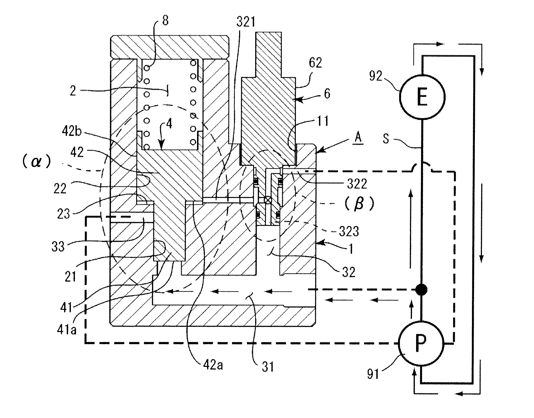
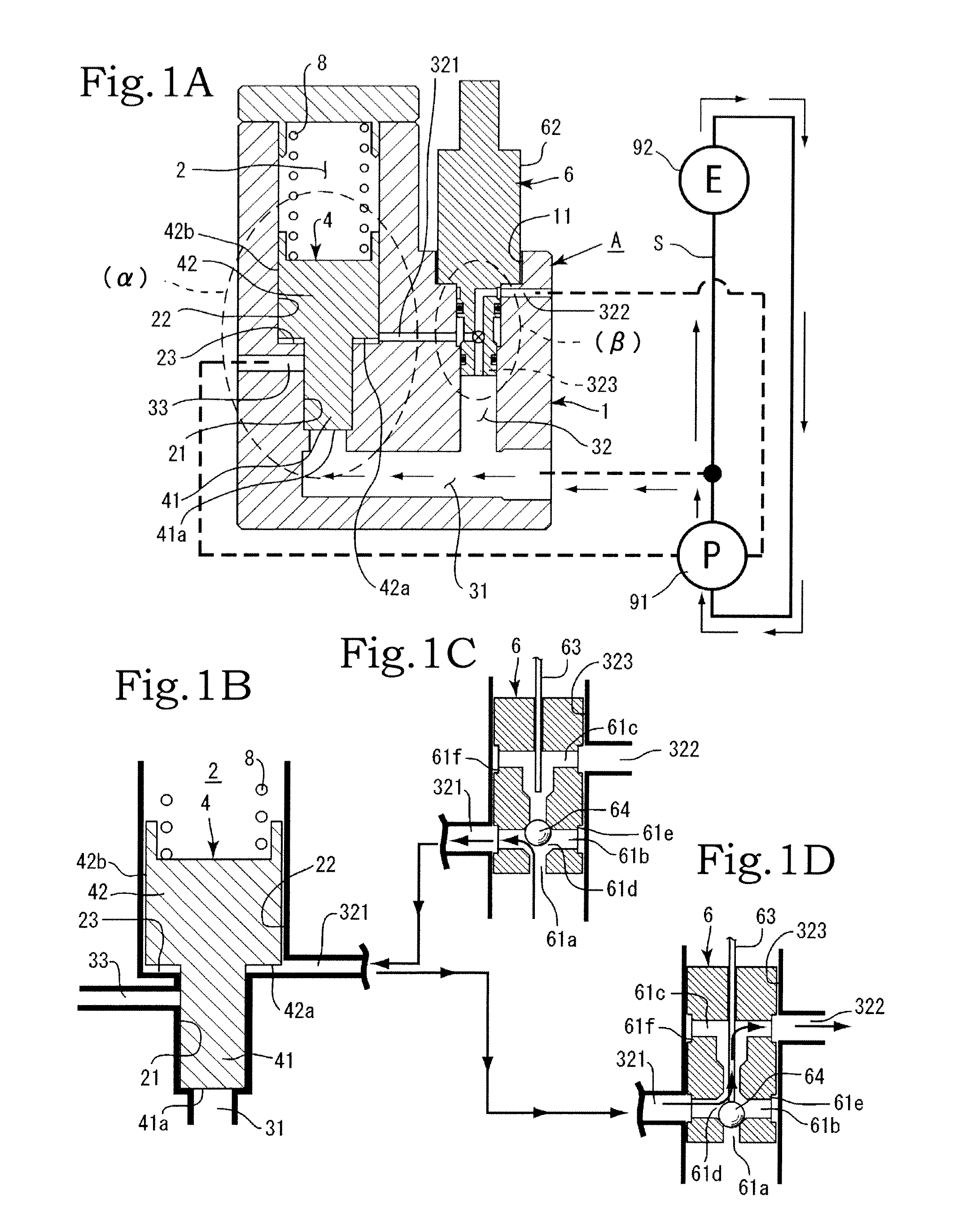
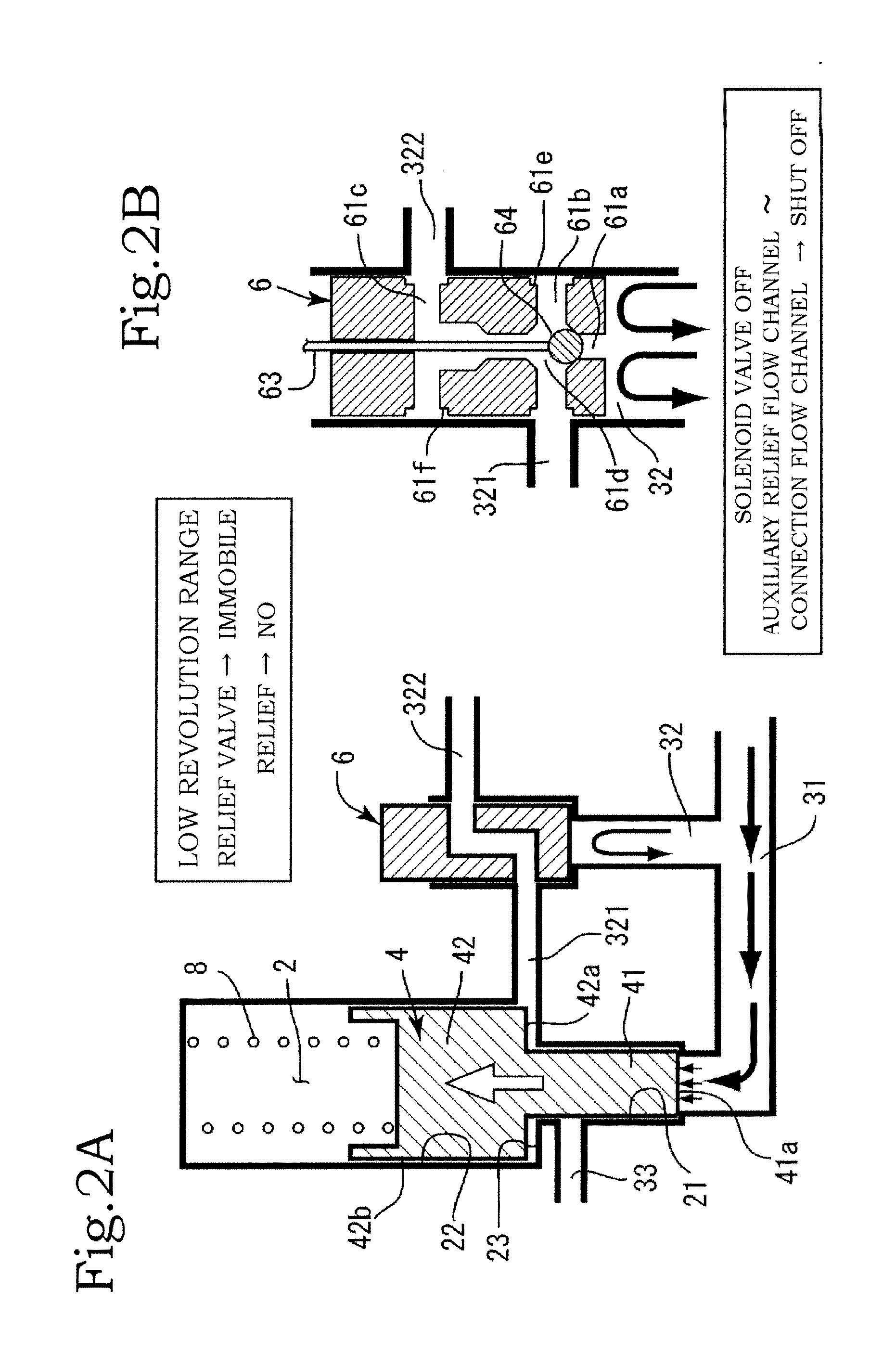
[0026]Embodiments of the present invention are described below with reference to accompanying drawings. The present invention has a plurality of embodiments. A first embodiment will be explained first. The configuration of the present invention comprises mainly a housing A, a solenoid valve 6, a relief valve 4 and a spring 8. The solenoid valve 6 is mounted on a chassis 1 of the housing A. The relief valve 4 is accommodated in the chassis 1 (FIG. 1A).

[0027]In the chassis 1 there are formed, for instance, a valve passage 2, a main relief flow channel 31, an auxiliary relief flow channel 32 and the like. The valve passage 2 is a site at which the relief valve 4 is accommodated. The valve passage 2 comprises a small-diameter passage section 21 and a large-diameter passage section 22 that are formed as coaxial cylindrical shapes having dissimilar inner diameters. Specifically, the large-diameter passage section 22 having a large diameter dimension is formed on the opening side, and the ...

second embodiment

[0063]the present invention is explained next with reference to FIG. 8. An in-valve flow channel 43 is formed inside the relief valve 4. The in-valve flow channel 43, specifically, is a flow channel that is formed extending from the main pressure-receiving surface 41a of the small-diameter section 41 over the outer peripheral side face 42b of the large-diameter section 42 (for instance, FIGS. 8A, 8C).

[0064]The in-valve flow channel 43 is made up of an axial direction flow channel 43a and a diameter-direction flow channel 43b, such that the axial direction flow channel 43a and the diameter-directs channel 43b communicate with each other. A flow channel opening of the axial direction flow channel 43a is positioned at the main pressure-receiving surface 41a of the small-diameter section 41, and flow channel openings of the diameter-direction flow channel 43b are positioned at the outer peripheral side face 42b of the large-diameter section 42.

[0065]The function (effect) of the in-valve...


PUM


Abstract

The invention allows securing greater discharge pressure and flow rate at high revolutions of an engine in order to secure lubrication and cooling, while reducing discharge pressure and flow rate at low and medium revolutions of the engine in order to improve efficiency. The invention includes a housing; a relief valve; a valve passage; a main discharge flow channel; a main relief flow channel; an auxiliary relief flow channel; a solenoid valve mounted on the auxiliary relief flow channel; and a spring. The solenoid valve is controlled so as to switch between communication and shut-off between the auxiliary relief flow channel and the large-diameter passage section in accordance with an increase or decrease in engine revolutions, and oil in the large-diameter passage section is discharged when the shut-off is implemented.

Description

BACKGROUND OF THE INVENTION[0001]1. Field of the Invention[0002]The present invention relates to a relief valve device, in an oil pump of, for instance, an engine for vehicles, that allows securing greater discharge pressure and flow rate at high revolutions of an engine in order to secure lubrication and cooling, while reducing discharge pressure and flow rate at low and medium revolutions of the engine in order to improve efficiency.[0003]2. Description of the Related Art[0004]Conventional relief valves that modify relief pressure depending on the magnitude of engine revolutions (high-low revolutions) have been disclosed (Japanese Patent Application Publication No. H5-26024) wherein a first relief pressure and a second relief pressure are set in accordance with the magnitude of engine revolutions (high-low revolutions). Japanese Patent Application Publication No. H5-26024 (FIG. 2) discloses a relief valve that has a solenoid valve 19, as well as a mechanical relief valve that comp...

Claims


Application Information

Patent Timeline
Patent Type & Authority Applications(United States)
IPC IPC(8): F16K31/36
CPCF16K31/1221F16K31/406F01M1/16Y10T137/776Y10T137/7761Y10T137/7762Y10T137/7782Y10T137/86614
Inventor WATANABE, MANABUMIYAJIMA, JUNICHI
Owner YAMADA SEISAKUSHO KK
Why Eureka
Try Eureka