

Stabilizer link for a vehicle suspension and method for obtaining it
- Summary
- Abstract
- Description
- Claims
- Application Information
AI Technical Summary
Benefits of technology
Problems solved by technology
Method used
Image

Examples
Embodiment Construction
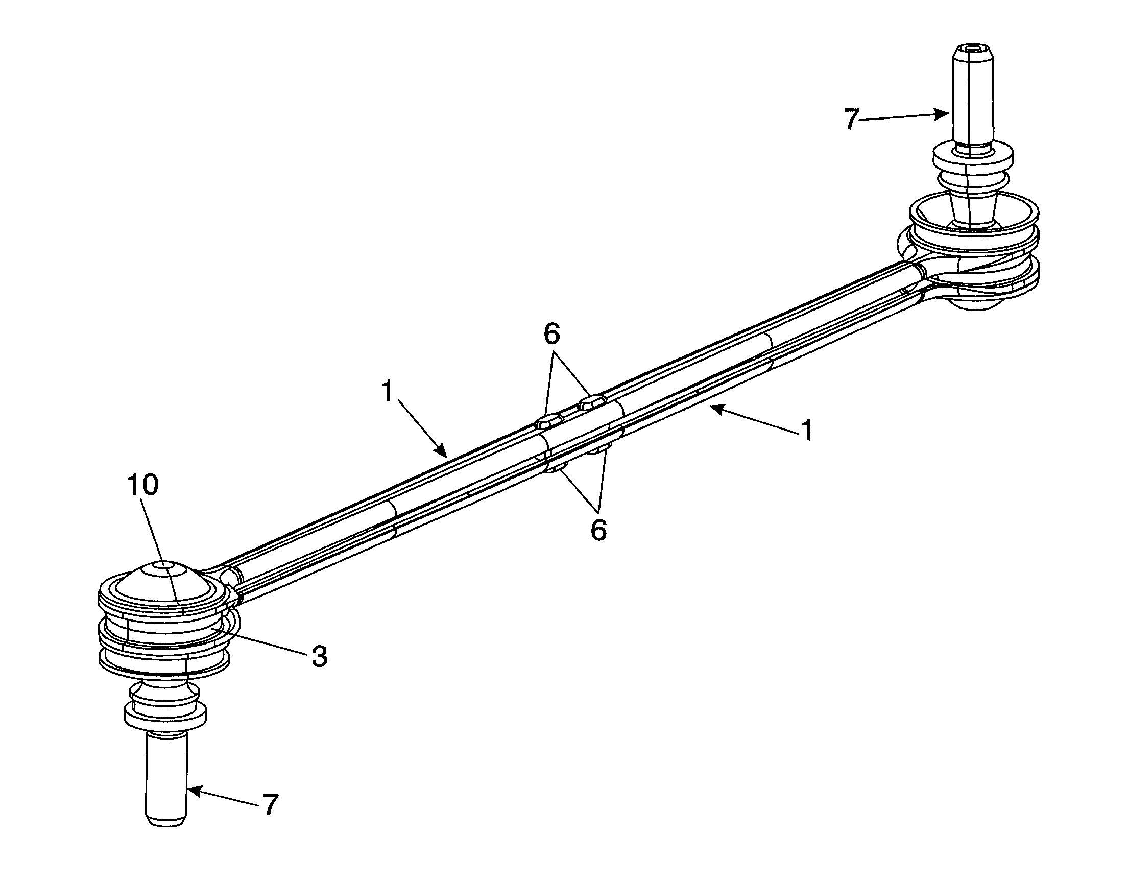
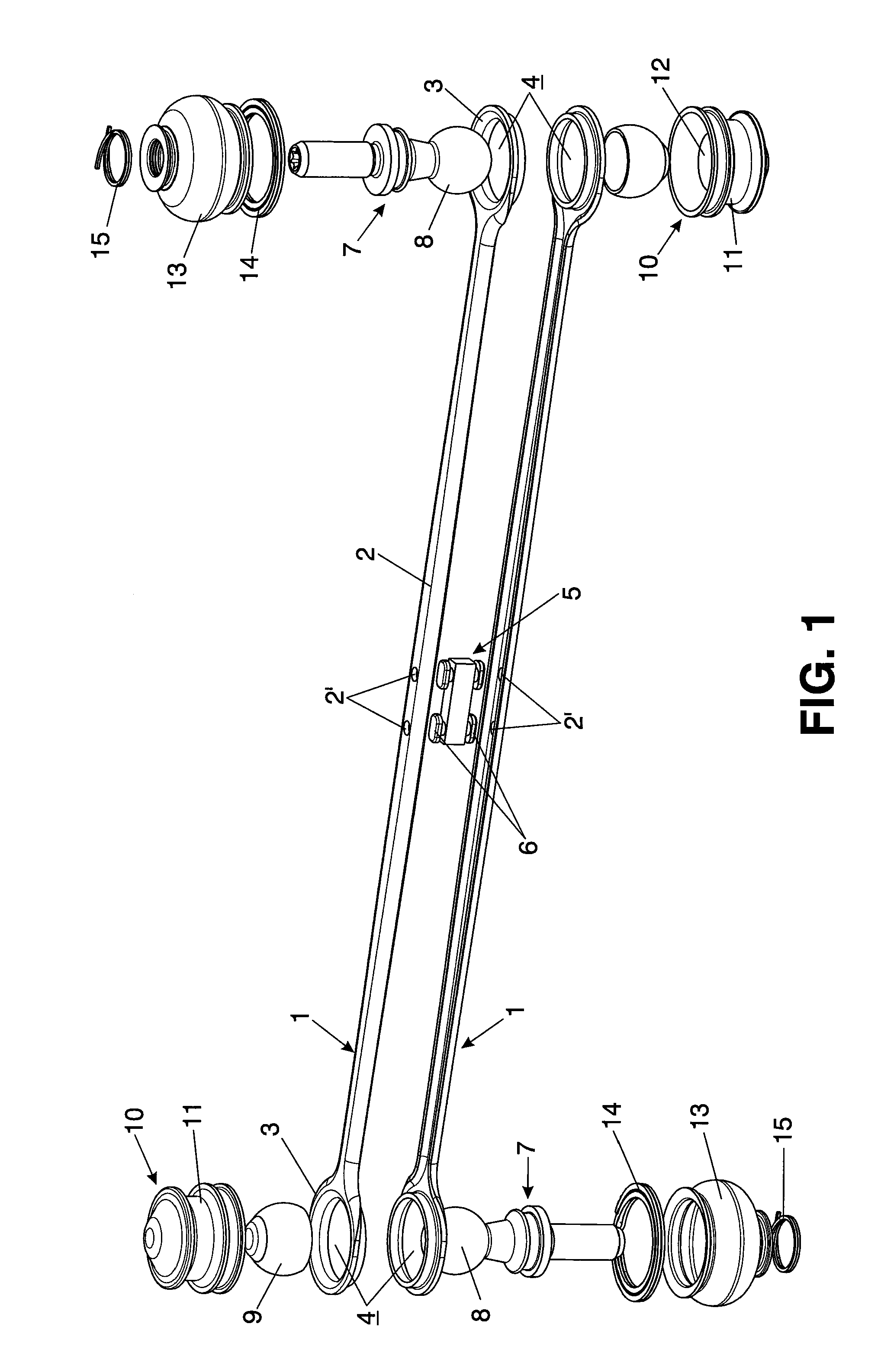
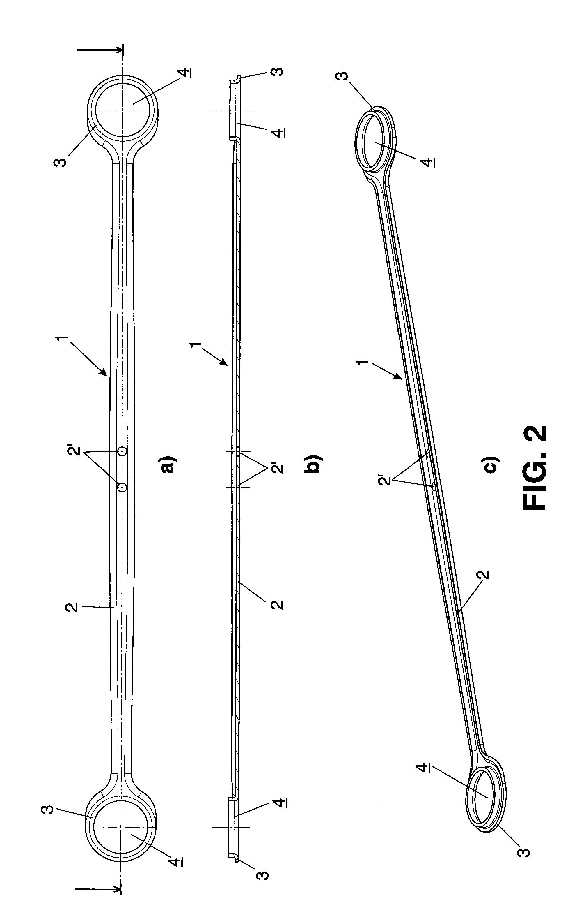
[0029]In view of the discussed figures, it can be observed how in one of the possible embodiments of the invention the stabilizer link for a vehicle suspension proposed by the invention comprises a longitudinal body having two ends (3) and a central sector (2), having at each end (3) a hole (4) in which an articulation element (7) is housed.
[0030]The longitudinal body is formed from two identical parts (1) which are arranged such that they are facing one another and remain attached by means of at least one plastically deformable attachment element (5) such that once it is deformed, it prevents the separation of the parts (1).
[0031]Each part (1) likewise comprises at least one central hole (2′) located in the central sector (2), where the central sector (2) of the parts (1) is hollow, the attachment element consisting of a central attachment element (5) which is housed inside the central sectors (2) of the facing parts (1).
[0032]The central attachment element (5) comprises at least t...
PUM
| Property | Measurement | Unit |
|---|---|---|
| Fraction | aaaaa | aaaaa |
Abstract
Description
Claims
Application Information