
Multistage centrifugal compressor

a centrifugal compressor and multi-stage technology, applied in the direction of machines/engines, stators, liquid fuel engines, etc., can solve the problems of high cost, high assembly difficulty of the half-diaphragm in the tank, and inability to seal the parts,

Active Publication Date: 2009-03-31
NUOVO PIGNONE TECH SRL
View PDF9 Cites 2 Cited by
  • Summary
  • Abstract
  • Description
  • Claims
  • Application Information

AI Technical Summary

Benefits of technology

[0028]The objective of the present invention is to provide a multistage centrifugal compressor which is simple and with reduced costs and production times.
[0029]A further objective is to provide a multistage centrifugal compressor having reduced costs and assembly times.
[0030]Another objective is to provide a multistage centrifugal compressor which allows a higher safety level during maintenance operations.
[0031]A further objective is to provide a multistage centrifugal compressor which allows the dimension of the bridge-crane, necessary for assembling the multistage centrifugal compressor, to be reduced.
[0033]A further objective is to provide a multistage centrifugal compressor which allows reduced maintenance costs and times.

Problems solved by technology

This is due to the fact that the half-diaphragms undergo axial stress during the functioning of the compressor and, without the supporting rings, they would tend to move, causing, among other things, sealing problems among the various stages.
The assembly of the half-diaphragms in the tanks is extremely difficult, as it is necessary to centre all the half-diaphragms with the respective half-rings and also to centre the lower half-diaphragms with the corresponding upper half-diaphragms.
One of the disadvantages is that costly lifting systems are necessary, capable of lifting the total weight of the upper tank on which the upper half-rings have been welded and the upper half-diaphragms respectively fixed to the upper half-rings.
Another disadvantage is that it is not possible to effect controls on the positioning of the components inside the tank.
A further disadvantage is that in the case of particularly large and heavy machines, the overturning of the upper tank requires costly and complex equipment.

Method used


Image

  • Multistage centrifugal compressor
  • Multistage centrifugal compressor

Examples


Embodiment Construction

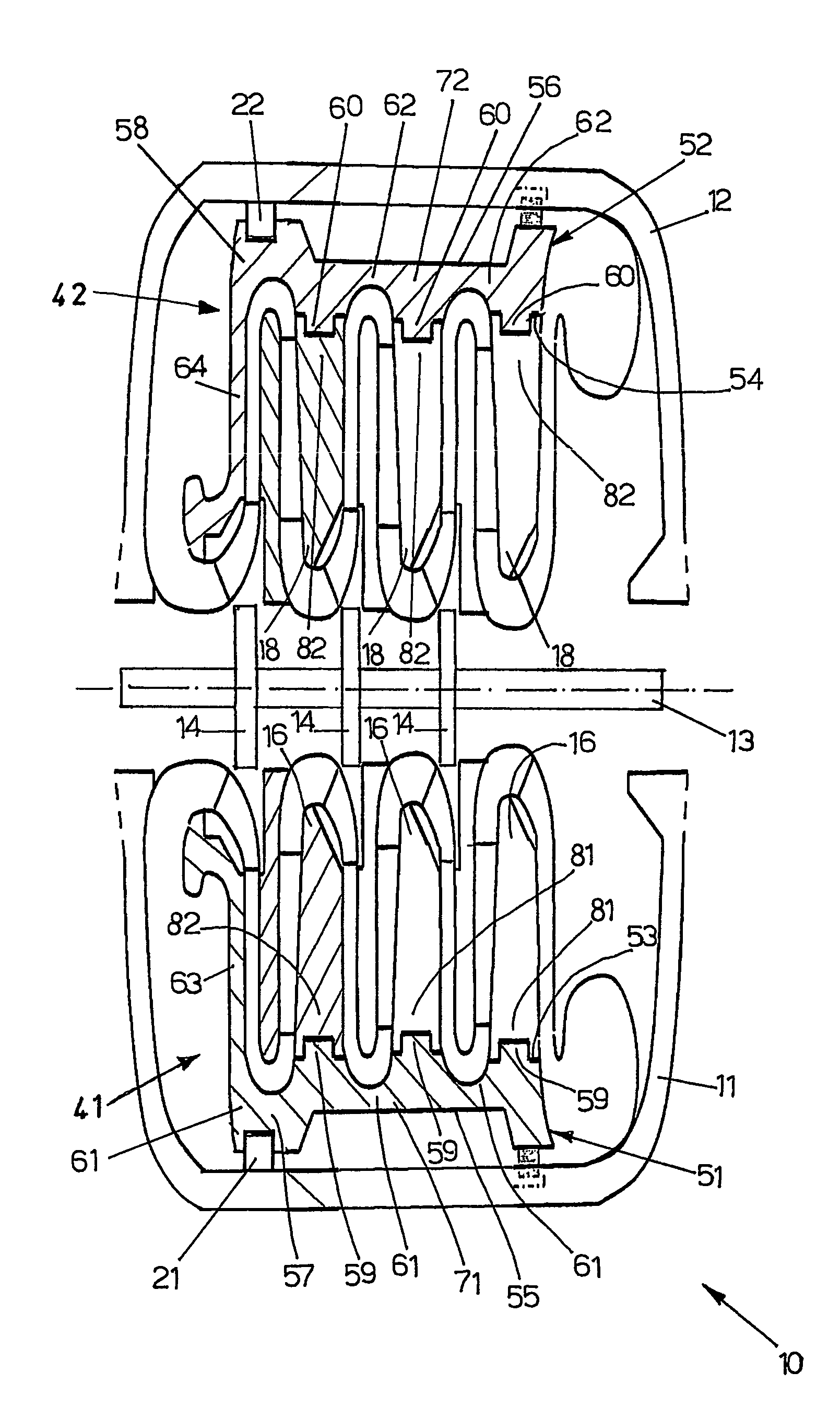
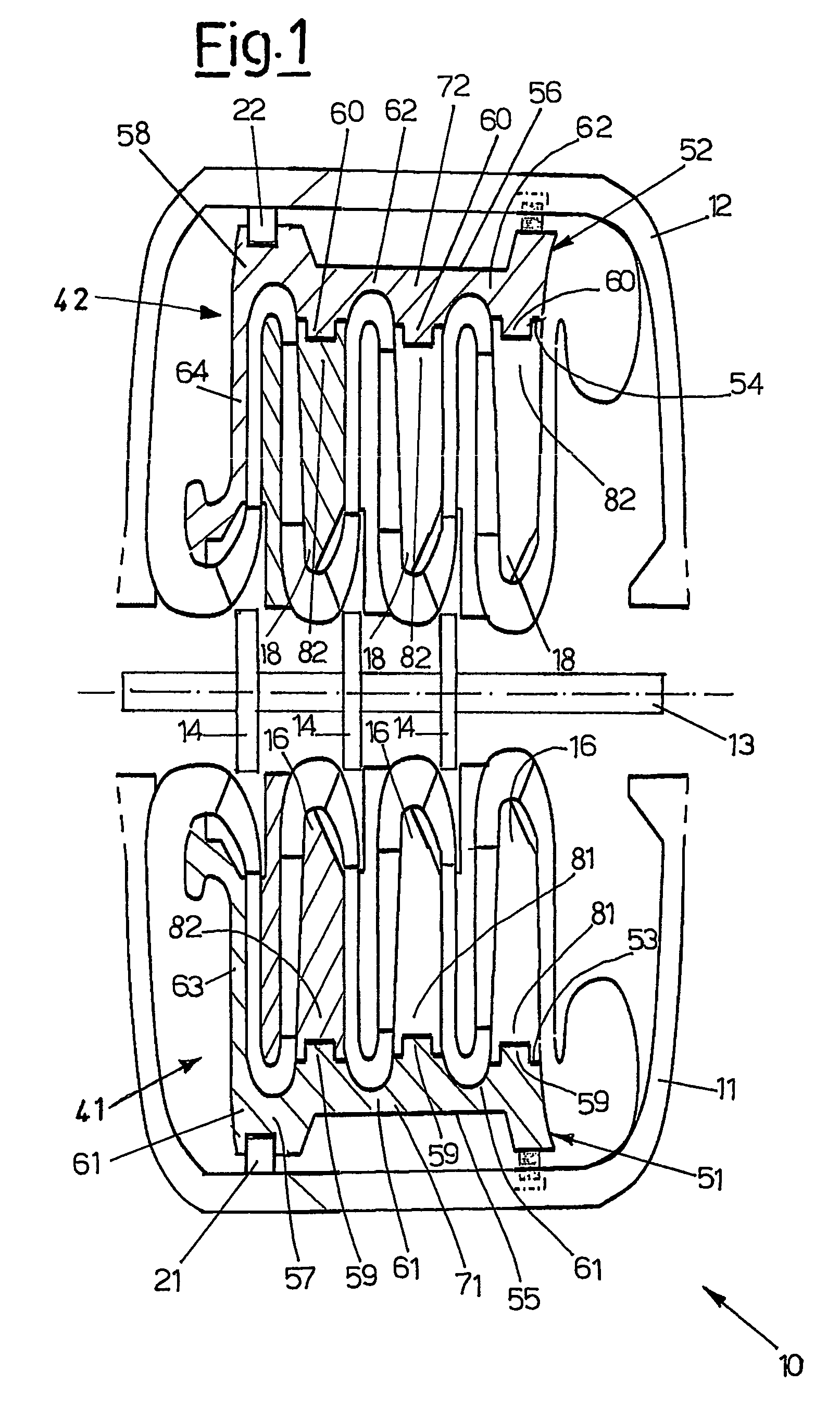
[0037]With reference to the figures, these show a multistage centrifugal compressor comprising at least one stage 10, which includes a lower half-tank 11 and an upper half-tank 12, a shaft 13 equipped with a series of rotors 14, a series of lower half-diaphragms 16, a series of upper half-diaphragms 18, a lower suction half-diaphragm 51 and an upper suction half-diaphragm 52.

[0038]The at least one stage 10 preferably comprises also a lower half-ring 21 and an upper half-ring 22 fixed to the lower half-tank 11 and to the upper half-tank 12, respectively.

[0039]In the at least one stage 10, the lower half-diaphragms 16 and the lower suction half-diaphragm 51 are packed and rigidly constrained to one another so as to form a first pile 41 of lower half-diaphragms.

[0040]Correspondingly, in the at least one stage 10, the upper half-diaphragms 18 and the upper suction half-diaphragm 52 are piled up and tightly constrained to one another so as to form a second pile 42 of upper half-diaphragm...


PUM


Abstract

Multistage centrifugal compressor includes at least one stage which, in turn, has a lower half-tank, an upper half-tank, a series of lower half-diaphragms, a shaft equipped with a series of rotors, a series of upper half-diaphragms, a lower suction half-diaphragm, an upper suction half-diaphragm, the lower suction half-diaphragm and the upper suction half-diaphragm include a lower portion (71) and an upper portion (72), respectively, suitable for being coupled with the lower half-diaphragms and with the upper half-diaphragms, respectively, to form a first pile of lower half-diaphragms and a second pile of upper half-diaphragms, respectively.

Description

CROSS-REFERENCE TO RELATED APPLICATIONS[0001]Not ApplicableBACKGROUND OF THE INVENTION[0002]1. Field of the Invention[0003]The present invention relates to a multistage centrifugal compressor having a tank which can be opened horizontally.[0004]2. Description of the Related Art[0005]The fundamental elements forming a multistage centrifugal compressor are a shaft equipped with a series of rotors, rotating round the machine axis, and a series of diffusers and / or diaphragms with return channels between the various stages, integral with a tank which contains the compressor.[0006]Each rotor consists of a series of bladed disks; all rotors are assembled on the same shaft.[0007]A diffusor follows each rotor disk.[0008]Each diffusor is associated with a bladed return channel, which conveys the fluid to the subsequent rotor.[0009]The whole set of each rotor together with the relative diffusers and return channels forms a stage, which is separated from the adjacent ones by annular diaphragms ...

Claims


Application Information

Patent Timeline
Patent Type & Authority Patents(United States)
IPC IPC(8): F01D1/02F04D17/12F04D29/44F04D29/62
CPCF04D17/122F04D29/441F04D29/624
Inventor SARRI, FRANCO
Owner NUOVO PIGNONE TECH SRL
Learn More