
Connection point for communication device on appliance

a communication device and connection point technology, applied in the field of applications, can solve the problems of negatively affecting the appearance of the appliance, significant impact on the manufacturing assembly process,

Inactive Publication Date: 2012-09-27
HAIER US APPLIANCE SOLUTIONS INC
View PDF8 Cites 37 Cited by
  • Summary
  • Abstract
  • Description
  • Claims
  • Application Information

AI Technical Summary

Benefits of technology

The present invention provides a connection point apparatus for an appliance that allows for easy and unobtrusive access to the appliance's electronics. This requires little to no redesign of the appliance's electrical harnesses and provides a more convenient way to connect with the appliance. The technical effects of this invention include improved user experience and simplified installation.

Problems solved by technology

However, selection of a connection point for the DSM module could require a complete redesign of the electrical harness of the appliance, and significantly impact the manufacturing assembly process as well.
Finally, selection of such a connection point could negatively affect the appearance of the appliance.

Method used


Image

  • Connection point for communication device on appliance
  • Connection point for communication device on appliance
  • Connection point for communication device on appliance

Examples


first embodiment

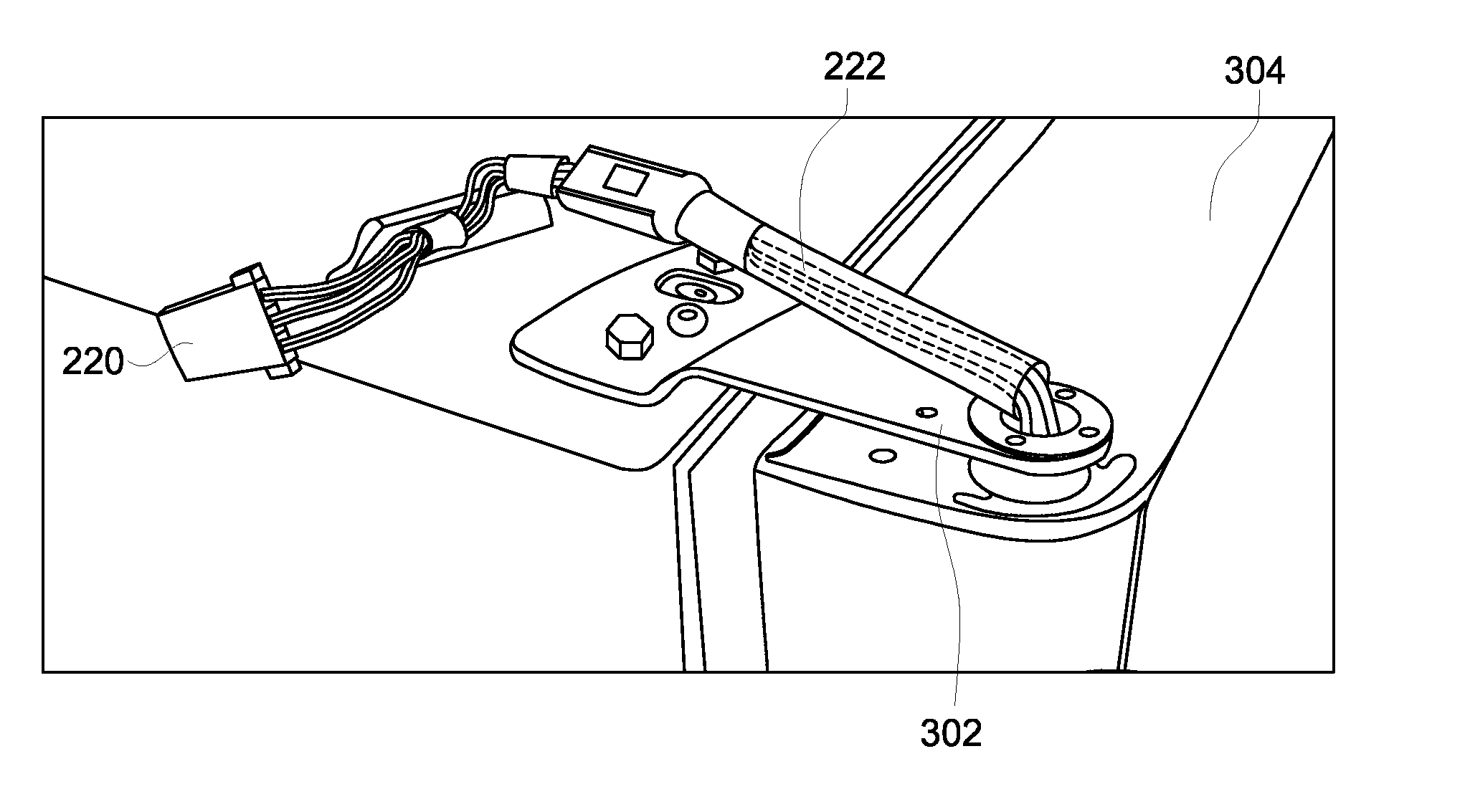
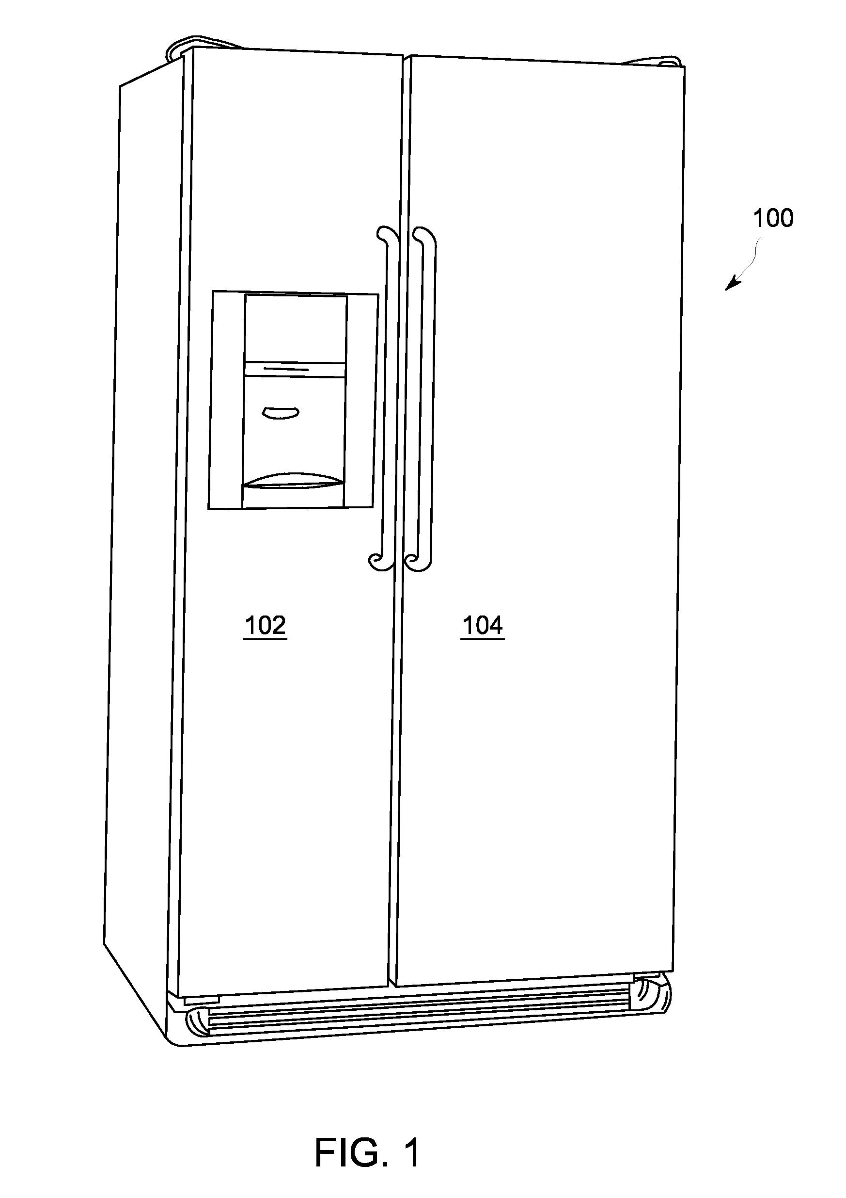
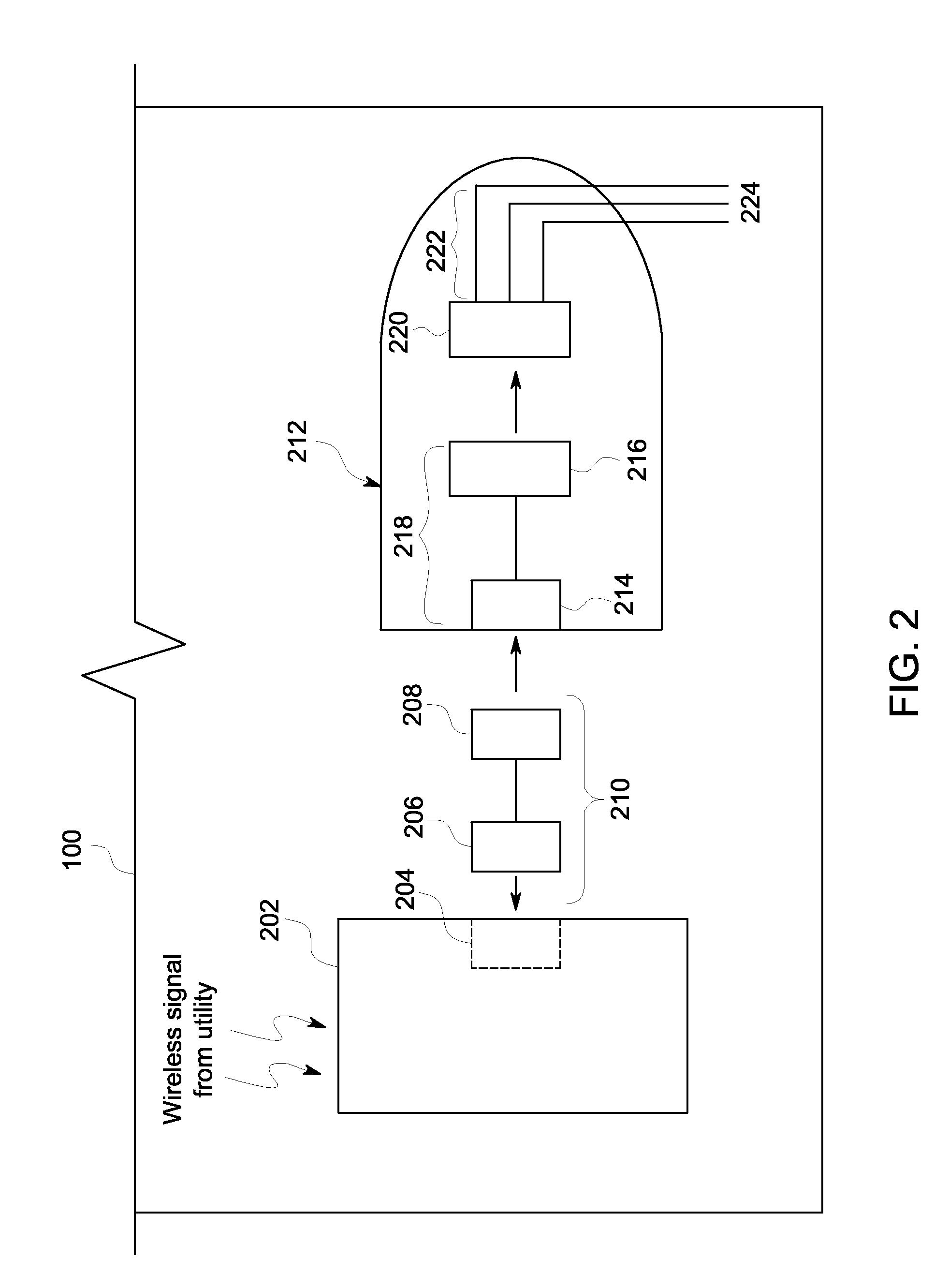
[0022]FIG. 2 illustrates a connection point for a communication device and a refrigerator appliance, in accordance with the invention. In the embodiment of FIG. 2, the connection point for a DSM module is the hinge cover on the top of the freezer door of a refrigerator. Thus, in the case of the side-by-side refrigerator 100 in FIG. 1, the hinge cover can be seen at the top left side of the door of the freezer portion 102. Advantageously, by modifying the hinge cover, a mounting cutout is added that allows an electrical connector to be mounted therein. The hinge cover can then be installed in the typical fashion, on top of the hinge that holds the freezer door to the body of the refrigerator, giving external access for a DSM module to be connected to the refrigeration control circuitry. It is to be understood that the hinge cover on top of the fresh food compartment 104 could alternatively be used for the connection point, rather than the freezer portion hinge cover.

[0023]Thus, as sh...

second embodiment

[0031]FIG. 7 illustrates a connection point for a communication device and a refrigerator appliance, in accordance with the invention. In the embodiment of FIG. 7, the connection point for a DSM module is machine compartment of the refrigerator 100. As is known, the machine compartment is an area in the back of the refrigerator at the bottom by the floor. By installing a bracket for mounting an electrical connector to the body of the refrigerator near the machine compartment, the DSM module can be connected to the control circuitry in an unobtrusive location, i.e., behind the refrigerator.

[0032]As shown in FIG. 7, a bracket 732 is mounted to the refrigerator case down by the machine compartment 730. The bracket 732 is held to the case by a fastener 734 and has an opening 736 for accepting the mounting of an electrical connector. Note that the remaining components numbered in FIG. 7 that have the same function as like components in the embodiment of FIG. 2 are numbered similarly but ...


PUM

PropertyMeasurementUnit
temperaturesaaaaaaaaaa
energyaaaaaaaaaa

Abstract

A connection point apparatus comprising an appliance door hinge cover; and an electrical connector mounted in an opening formed in the appliance door hinge cover and configured to accept an electrical connector connected to a communication device used to communicate with the appliance. Another connection point apparatus comprising an appliance machine compartment bracket; and an electrical connector mounted in an opening formed in the appliance machine compartment bracket and configured to accept an electrical connector connected to a communication device used to communicate with the appliance.

Description

BACKGROUND OF THE INVENTION[0001]The subject matter disclosed herein relates to appliances, and more particularly to mounting a connection point for a communication device on such an appliance.[0002]One example of a communication device that may require connection to an appliance is a device known as a demand side management (DSM) module. As is known, demand side management is a form of energy demand management that involves an electric utility company remotely controlling the quantity or patterns of use of energy consumed by end users with respect to their appliances. For example, a refrigerator appliance may be fitted with a DSM module that wirelessly receives transmitted commands from the electric utility company that serve to control the energy use of the refrigerator during periods when the energy supply network is constrained. That is, in response to received commands, the DSM module may cause a reduction in the energy use of the refrigerator by increasing the thermostat setti...

Claims


Application Information

Patent Timeline
Patent Type & Authority Applications(United States)
IPC IPC(8): F25D23/02H01R13/40H01R43/00E05D11/00
CPCH01R24/64H01R35/02Y10T29/49117F25D2400/40Y10T16/522F25D23/00
Inventor MERSHON, MARTINGARDNER, JOHNMASHAL, KHALIDMAYNE, JOSHUA
Owner HAIER US APPLIANCE SOLUTIONS INC
Learn More