3-d video processing device and 3-d video processing method

Inactive Publication Date: 2012-09-27
PANASONIC INTELLECTUAL PROPERTY MANAGEMENT CO LTD
View PDF6 Cites 13 Cited by
  • Summary
  • Abstract
  • Description
  • Claims
  • Application Information

AI Technical Summary

Benefits of technology

[0028]With the 3D image processing device of the present embodiment, an image process according to a parallax of an object of a 3D image is perfor

Problems solved by technology

However, in some cases, each of the cameras is oversized and the cameras cannot be installed with an interval of 65 mm.
Therefore, the shooting of a 3D image requires many techniques and a large amount of know-how.
It has been pointed out that, when the stereoscopic effect of the 3D image is inappropr

Method used


Image

  • 3-d video processing device and 3-d video processing method
  • 3-d video processing device and 3-d video processing method
  • 3-d video processing device and 3-d video processing method

Examples


first embodiment

1. First Embodiment

[0044]1-1. Overview

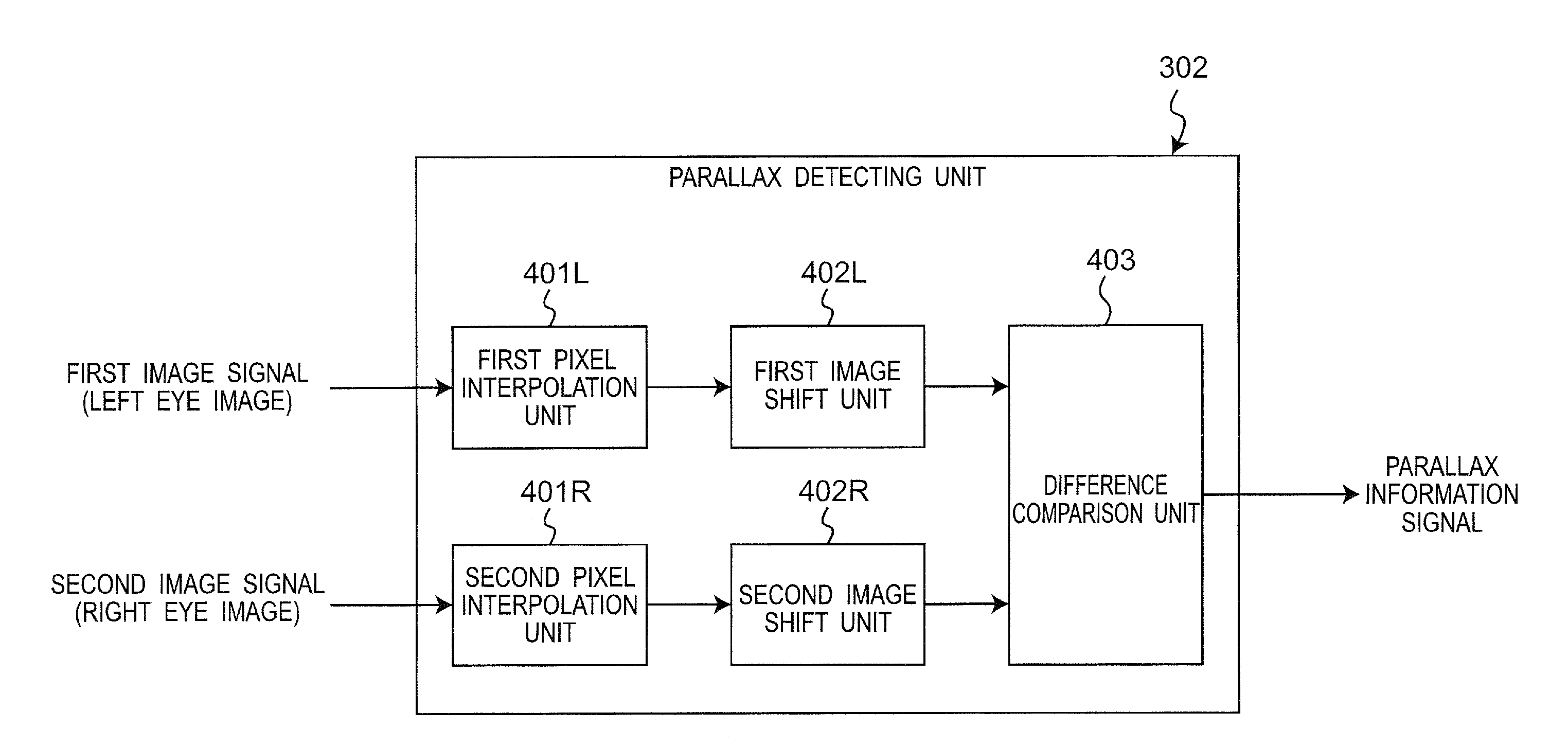
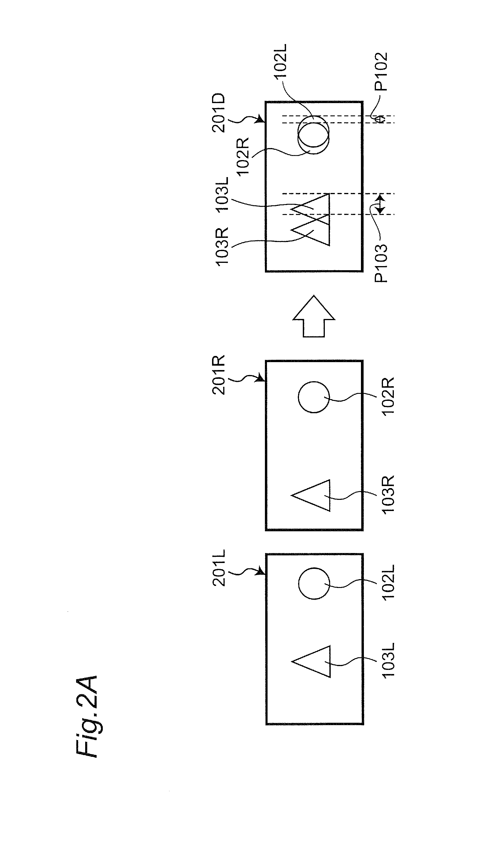
[0045]A 3D image processing device according to the present embodiment is a 3D image processing device that can output an image with which whether or not a 3D image is a natural 3D image that brings no discomfort can easily be determined. More specifically, the present 3D image processing device detects a parallax between a left eye image and a right eye image as to an object in a 3D image, and based on the detected parallax, detects an image region of an object in the image which is highly possible to discomfort an observer. Then, the 3D image processing device provides a predetermined image process, e.g., a marker display processing or the like for enhancing the image region, to the detected image region of the object, and outputs the processed result.

[0046]The image that has undergone the marker display processing or the like allows an observer to easily recognize the image region which is highly possible to discomfort the observer, and to de...

second embodiment

2. Second Embodiment

[0096]2-1. Overview

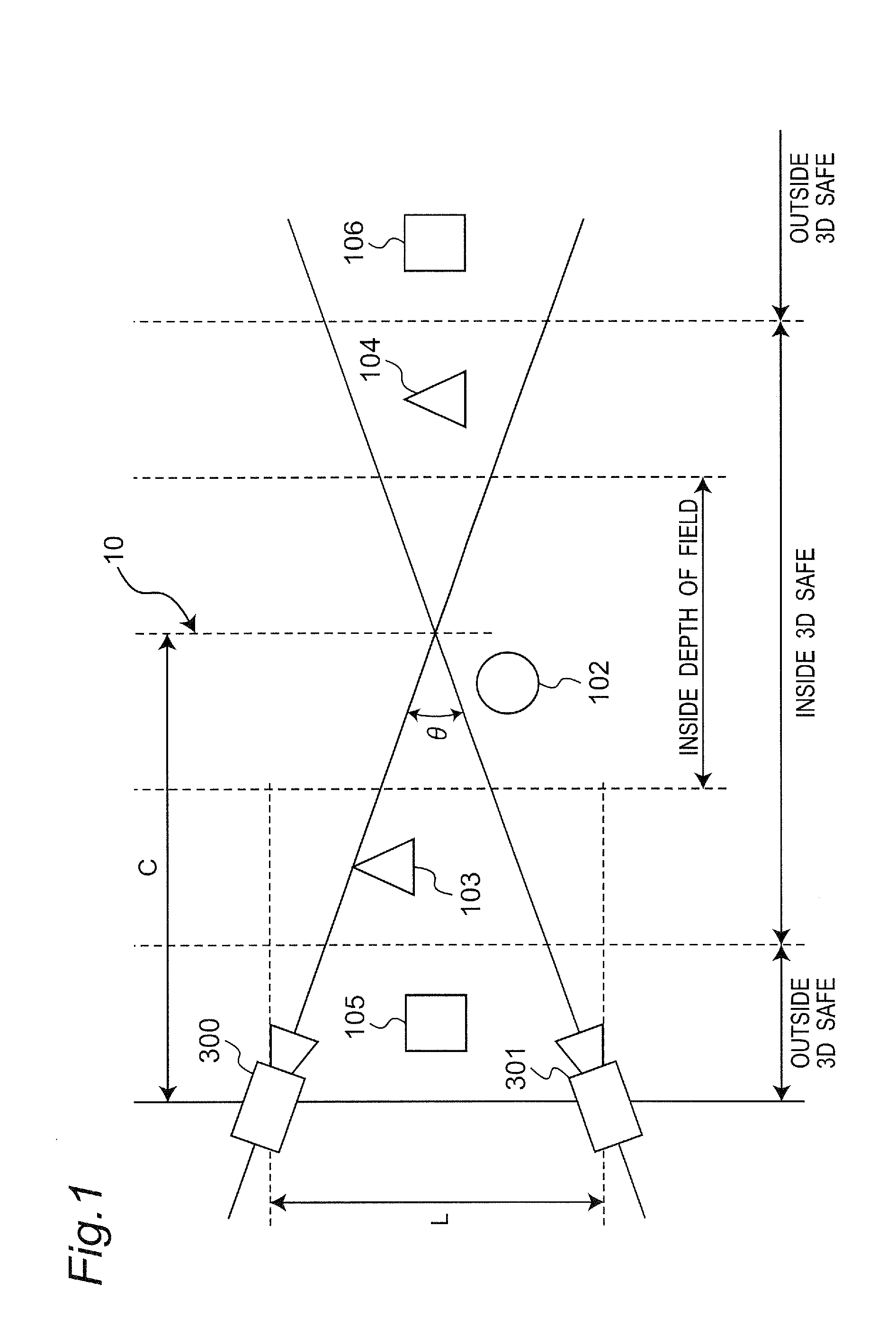
[0097]A 3D image processing device according to the present embodiment includes, in addition to the structure of the 3D image processing device 310 according to the first embodiment, a structure of detecting a distance to an arbitrary object. Based on the detected distance, whether or not the object is included in the depth of field is determined. The determination result is reflected in the marker display in the overlaid image output to the display unit 305. It is to be noted that, the depth of field is derived based on the setting information of the camera.

[0098]Thus, the observer watching the display unit 305 can easily recognize whether or not the object in the image is in the depth of field. An object being included in the depth of field and the parallax of the object being included in the predetermined range are not necessarily equal. However, an object being included in the depth of field strongly indicates that a 3D image that is natura...

third embodiment

3. Third Embodiment

[0125]3-1. Overview

[0126]A 3D image processing device according to the present embodiment is a 3D image processing device that processes a 3D image, to thereby perform a predetermined process to an object outside 3D safe, such that the 3D image can be turned into a 3D image that is natural and brings no discomfort. More specifically, the 3D image processing device performs a defocus processing to an object outside 3D safe in a 3D image and outputs the result.

[0127]Thus, in the 3D image having undergone the defocus process, an object outside 3D safe has its contour or the content detail defocused. Thus, it is less prone to discomfort the observer.

[0128]The 3D image processing device according to the present embodiment may have a similar configuration as the 3D image processing devices 310 and 710 according to the first and second embodiments, respectively. In the following description, reference and description as to the marker generating unit 303, the overlay unit...


PUM


Abstract

A 3D image processing device capable of processing a 3D image signal, the 3D image signal including a left eye image signal and a right eye image signal and realizing a 3D The 3D image processing device includes: a parallax detecting unit operable to receive the left eye image signal and the right eye image signal, detect a parallax of an object within the 3D image, and output the detected parallax as parallax information; and an image processing unit operable to perform, based on the parallax information, a predetermined image processing to an image region of an object of at least one of the left eye image signal and the right eye image signal, the object having a parallax within a predetermined range.

Description

TECHNICAL FIELD[0001]The present invention relates to a 3D image processing device and a 3D image processing method for processing a stereoscopically viewable image (a 3D image), and in particular, to a 3D image processing device and a 3D image processing method that assists 3D image creation.BACKGROUND ART[0002]Attention is being given to 3D image imaging devices that shoot images to be presented respectively to the left eye and the right eye of an observer (i.e., a left eye image and a right eye image), to thereby generate a stereoscopically viewable image signal (a 3D image signal).[0003]It is known that, by adjusting the arrangement of a left eye image camera (a left eye image imaging unit) that images a left eye image and a right eye image camera (right eye image imaging unit) that images a right eye image, the magnitude of the stereoscopic effect of a 3D image can be changed. That is, by adjusting arrangement of the two cameras, the magnitude of the parallax of an object inclu...

Claims


Application Information

Patent Timeline
IPC IPC(8): H04N13/00
CPCG03B35/08H04N13/0239H04N13/0003H04N13/10H04N13/239
Inventor SAITO, HIROSHI
Owner PANASONIC INTELLECTUAL PROPERTY MANAGEMENT CO LTD
Why Eureka
Try Eureka